5.4 Connection
DANGER
D
e-energize the system!
The plant could inadvertently start while you are connecting the devices.
b
Make sure that the entire plant is disconnected from the voltage supply during all
electrical installation work.
Only use a suitable voltage supply!
The sensor must be connected to a voltage supply of protection class 2 SELV/PELV
24 V DC, +10 %/–15 %.
Prevent the formation of a potential difference between the load and the protective
device!
b
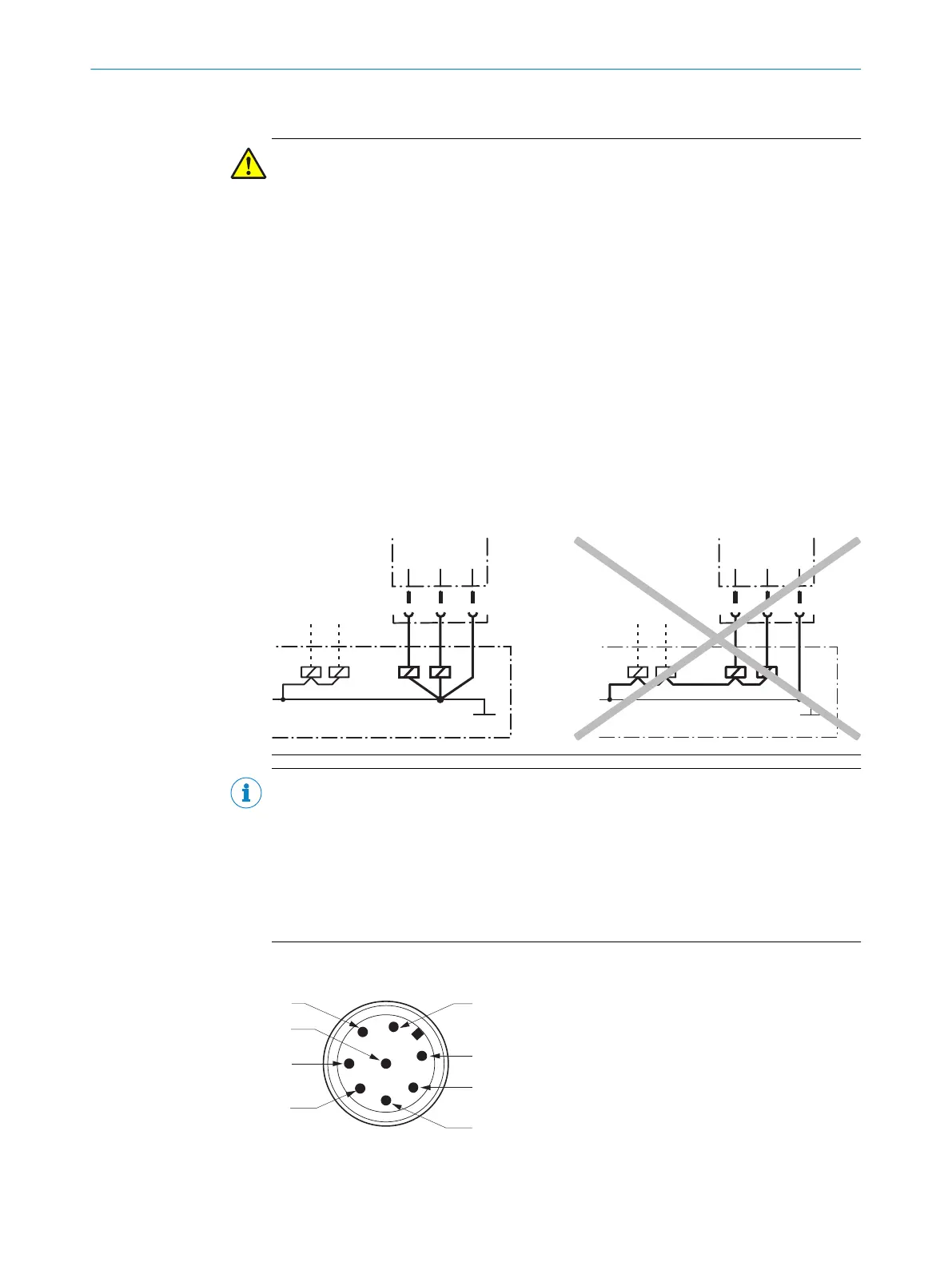
If you connect the loads to the OSSDs or safety outputs that do not have reverse
polarity protection, you must connect the 0 V connections of these loads and
those of the corresponding protective device separately and directly to the same
0 V terminal strip. In the event of a fault, this is the only way to ensure that there
can be no potential difference between the 0 V connections of the loads and
those of the corresponding protective device.
NOTE
•
T
he safety switch complies with the regulations for electromagnetic compatibility
(EMC) for the industrial sector (Radio Safety Class A). Radio interference cannot
be ruled out when used in residential areas.
•
In order to minimize network influences on the device behavior, the external volt‐
age supply of the devices (SELV/PELV) must be able to bypass events, including a
power outage of 20 ms. Power supply units according to EN 60204-1 fulfill this
prerequisite. Suitable power supply units are available as accessories from SICK.
5.4.1 Device connection (M12, 8-pin or cable variant)
Figure 3: Device connection (M12, 8-pin)
5 ELE
CTRICAL INSTALLATION
14
O P E R A T I N G I N S T R U C T I O N S | TR4 Direct Cylindrical 8022968/15V1/2019-11-22 | SICK
Subject to change without notice