Table 2: Pin assignment (M12, 8-pin) and cable assignment (cable variant)
Pin Wire color
1)
Designation Description
1 White Aux Application diagnostic output (not safe)
2 Brown 24 V DC Voltage supply 24 V DC
3 Green n. a. Not connected
4 Yellow In 2 Enable input for OSSD 2
2)
5 Gray OSSD 1 OSSD 1 output
6 Pink OSSD 2 Output OSSD 2
7 Blue 0 V Voltage supply 0 V DC
8 Red In 1 Enable input for OSSD 1
2)
1)
Applies to the connecting cables recommended as accessories.
2)
When using an individual safety switch or in a series connection with T-connector, apply 24 V DC on the
f
irst safety switch.
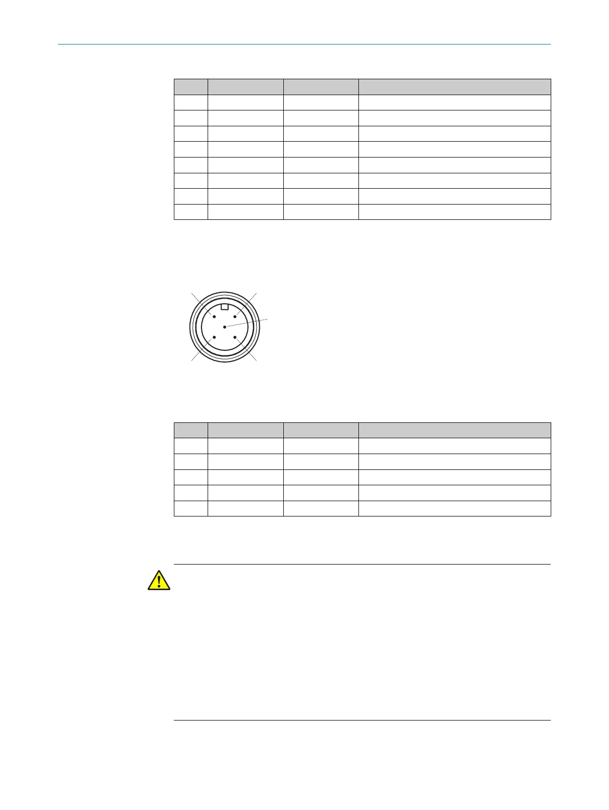
5.4.2 Device connection (M12, 5-pin)
Figure 4: Device connection pin assignment (M12, 5-pin)
T
able 3: Device connection pin assignment (M12, 5-pin)
Pin Wire color
1)
Designation Description
1 Brown 24 V DC Voltage supply 24 V DC
2 White OSSD 1 OSSD 1 output
3 Blue 0 V Voltage supply 0 V DC
4 Black OSSD 2 Output OSSD 2
5 Gray Aux Application diagnostic output (not safe)
1)
Applies to the connecting cables recommended as accessories.
5.4.3 Connecting an individual safety switch
DANGER
Use e
xternal device monitoring!
The safety switch does not feature external device monitoring. To reach SIL3/PL e, you
must therefore implement external device monitoring with the help of a suitable higher-
level safety evaluation.
The actually achieved performance level or safety integrity level depends on the exter‐
nal wiring, the wiring version, the selection of control switches and their arrangement
on the machine.
Evaluate both safety outputs!
Both safety outputs (OSSD 1 and OSSD 2) must be evaluated without fail in order to
guarantee safety.
ELECTRICAL INSTALLATION 5
8022968/15V1/2019-11-22 | SICK O P E R A T I N G I N S T R U C T I O N S | TR4 Direct Cylindrical
15
Subject to change without notice