5.4.4 Series connection of several safety switches
Several safety switches with cable or an 8-pin M12 connector can be safely connected
in ser
ies. The number of safety switches in a safe series connection is nearly limitless.
This has an influence the response times of the system, however. We therefore recom‐
mend using no more than 30 safety switches in a safe series connection.
DANGER
Use external device monitoring!
The safety switch does not feature external device monitoring. To reach SIL3/PL e, you
must therefore implement external device monitoring with the help of a suitable higher-
level safety evaluation.
The actually achieved performance level or safety integrity level depends on the exter‐
nal wiring, the wiring version, the selection of control switches and their arrangement
on the machine.
Evaluate both safety outputs!
Both safety outputs (OSSD 1 and OSSD 2) must be evaluated without fail in order to
guarantee safety.
Prevent manipulation!
If using T-connectors, you must mount the connecting cables so that simple bridging of
the safety switch is not possible.
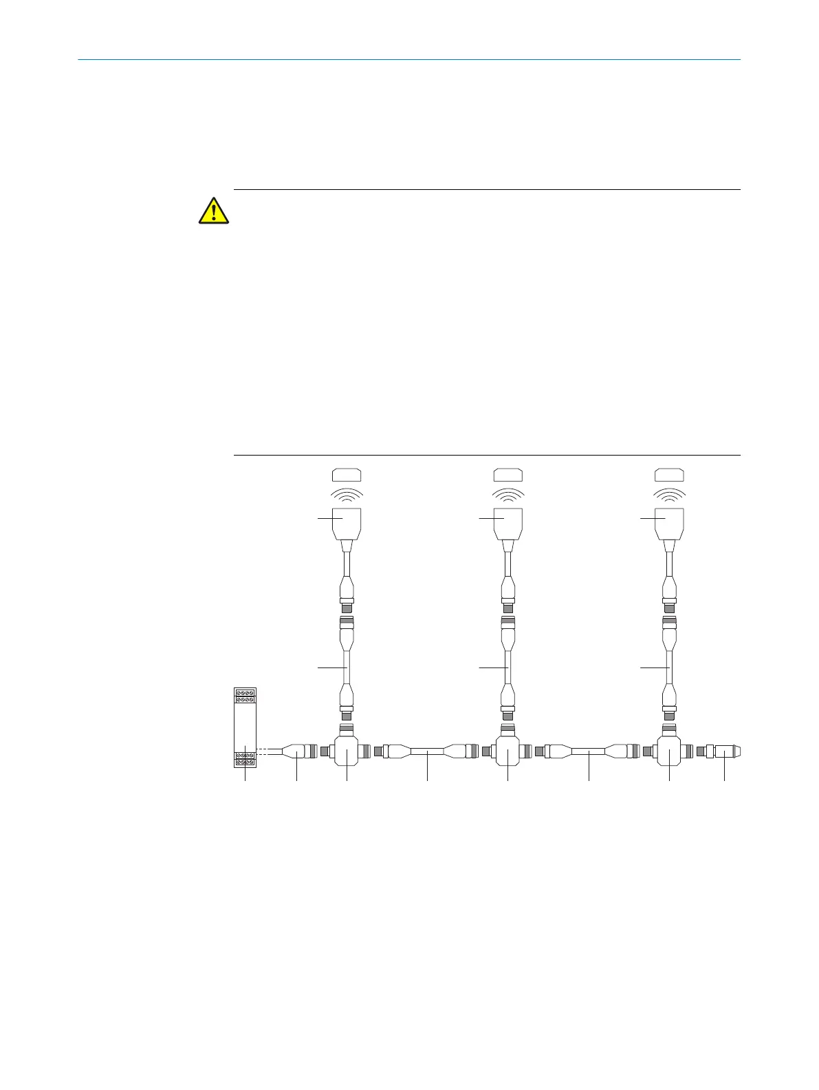
Figure 5: Safe series connection of several safety switches
1
Safe evaluation unit
2
Connecting cable with female connector, M12, 4-pin and flying leads (e.g. YF2A14-
xxxVB3XLE
AX)
3
T-connector STR-XXA
4
Connection cable with male connector, M12, 4-pin and female connector, M12, 4-pin (e.g.
YF2A14-xxxVB3M2A14)
5
End connector MLP1-XXT
6
Connection cable with male connector, M12, 8-pin, and female connector, M12, 8-pin
(e.g. YF2A18- xxxUA5M2A18)
7
TR4 Direct safety switch
5 ELE
CTRICAL INSTALLATION
16
O P E R A T I N G I N S T R U C T I O N S | TR4 Direct Cylindrical 8022968/15V1/2019-11-22 | SICK
Subject to change without notice