8.8.3 Pin 2 configuration
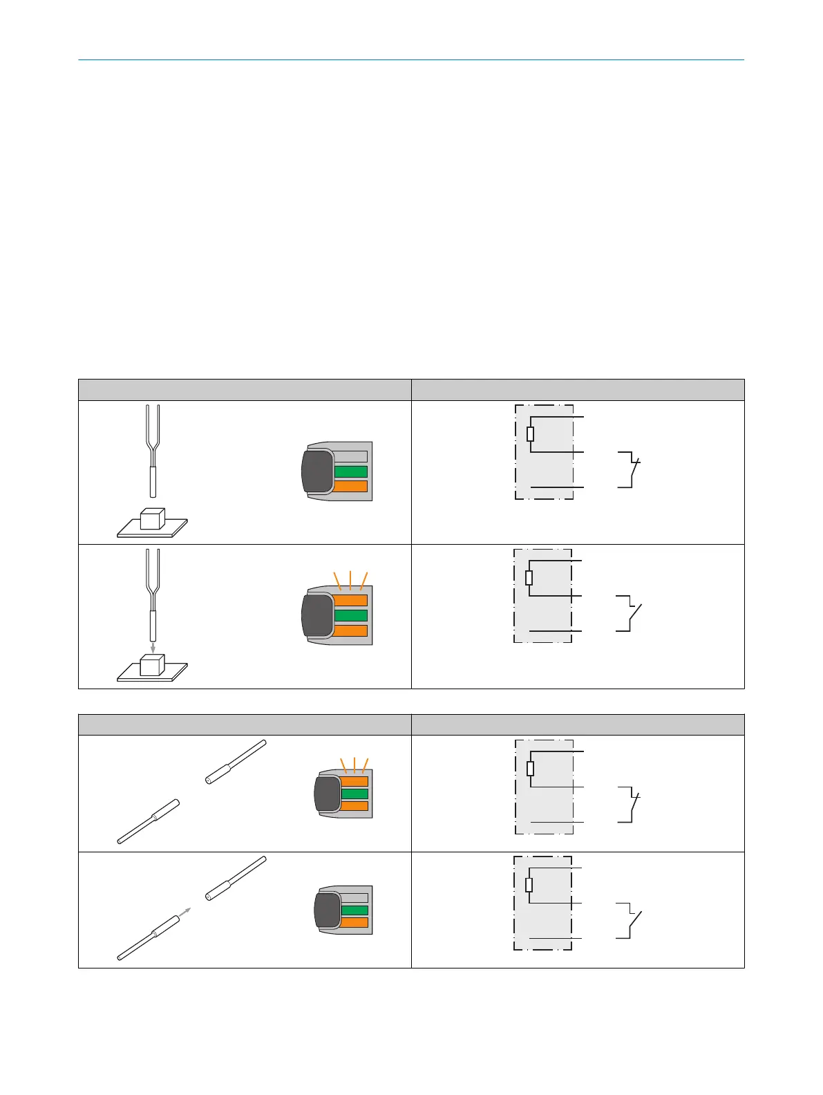
Test input
Test input: The WLL80 has a test input that can be used to switch off the sender and thereby check that the
sensor is functioning correctly: If female cable connectors with LED indicators are used, you must ensure that the
test input is assigned accordingly.
Proximity mode: If an object is detected, activate the test input (see the connection diagram [see table 39,
page 40], PNP: TE → M).
Sender LED is switched off. No object being detected is simulated.
Through-beam mode: There must be no object between the sender and receiver;activate the test input (see the
connection diagram, TI at 0V).
Sender LED is switched off. The detection of an object is simulated.
Use the following table to check the function. If the digital output fails to behave in accordance with the following
table, check the application conditions. See the Error analysis section.
Table 39: Test function for proximity
Test
Table 40: Test function for through-beam
Test
8 OPERATION
40
O P E R A T I N G I N S T R U C T I O N S | WLL80 Analog 8027947 /2022-12-14 | SICK
Subject to change without notice