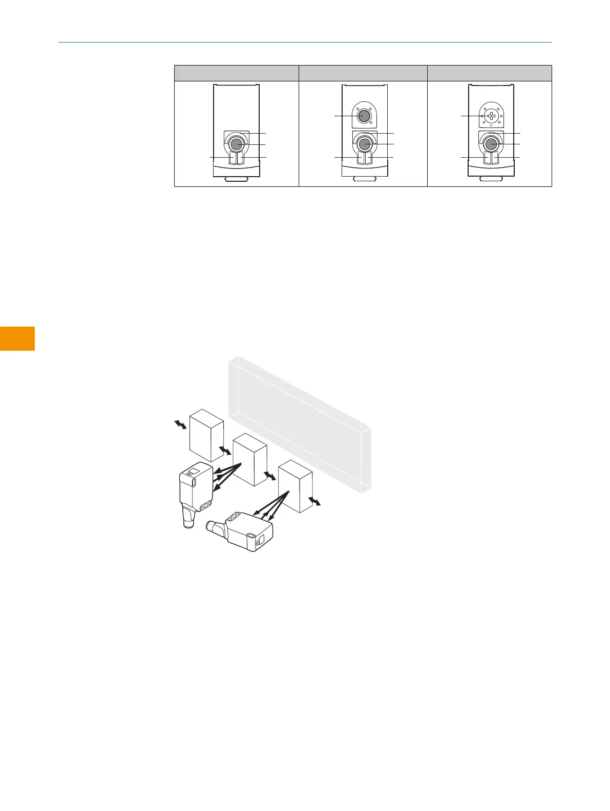
WTS26x-xxxxxx30 WTS26x-xxxxxx31 WTS26x-xxxxxx32
1
BluePilot blue: sensing range display
2
Press-turn element / Potentiometer / Teach-Button: adjusting the sensing range
3
Yellow LED: status of received light beam
4
Green LED: supply voltage active
5
Press-turn element: time function adjustment
6
Teach pushbutton: adjustment of light/dark switching
4 Mounting
Mount the sensorusing a suitable mounting bracket (see the SICK range of accesso‐
ries).
Note the preferred alignment of the sensor relative to the movement direction of the
object, see figure 1.
Figure 1: Alignment of the sensor relative to the object direction
Note the sensor’s maximum permissible tightening torque of < 1.3Nm.
5 Electrical installation
The sensors must be connected in a voltage-free state. The following information must
be observed, depending on the connection type:
– Male connector connection: Note pin assignment
– Cable: wire color
Only supply/switch on the voltage once all electrical connections have been estab‐
lished.
Explanations of the connection diagram (following tables):
Alarm = alarm output
OPERATING INSTRUCTIONS
28
O P E R A T I N G I N S T R U C T I O N S | WTS26 8020355.1GI9/2022-07-13 | SICK
Subject to change without notice
en