6 Commissioning
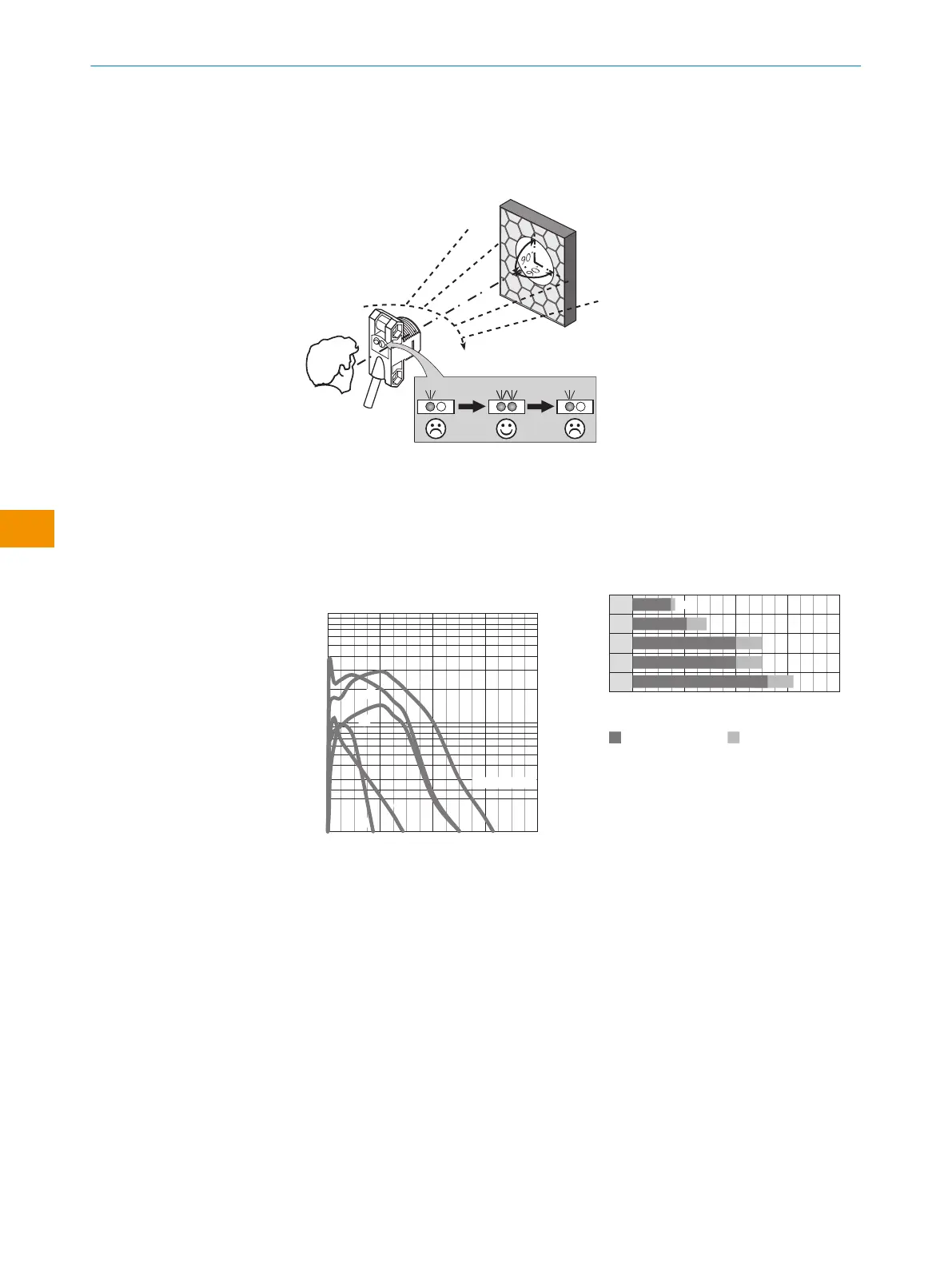
1 Alignment
Figure 2: Alignment
2 Sensing range
Adjust the distance between the sensor and the reflector according to the corresponding
diagram [see figure 3] (x = sensing range, y = operating reserve).
After alignment is complete, move a non-transparent object into the path of the beam. Use
table 1 to check the function. If the switching output fails to behave in accordance with
table 1, check the application conditions.
0
100
10
1
2
(6.56)
4
(13.12)
8
(26.24)
6
(19.68)
Function reserve
Distance in m (feet)
4
2
1
3
5
Sensing range
Figure 3: Characteristic curve
1
PL23FT
2
PL20A
3
P250
4
PL40A
5
PL80A
Sensing range Sensing range typ. max.
1
2
3
4
5
0
1.5
0
2.1 2.9
0
4.0 5.0
5.0
0
0
5.4 6.2
0
Distance in m (feet)
2
(6.56)
4
(13.12)
8
(26.24)
6
(19.68)
4.0
1.7
Figure 4: Bar graph
3 Sensitivity setting
Sensor not possible to be set: The sensor has been adjusted by the factory to provide
maximum sensitivity and is ready for operation.
OPERATING INSTRUCTION
26
O P E R A T I N G I N S T R U C TI O N | ZLD18 / ZLE18 8021946.1HW1 /2022-11-14 | SICK
Subject to change without notice
en