- 20 -
Tiller CS
5.3 CHECK THE STABILITY OF THE TRACTOR-TILLER
COMPLEX.
Tiller weight changes the stability of the tractor-Tiller complex, inuencing steering
and braking capability. Therefore proceed at a moderate speed. In particular, it
should be noted that the front axle must always be carrying a load of at least 20%
of the weight of the tractor-Tiller unit.
Check the lifting capacity and stability of the tractor using the following formula
and, if necessary, before applying the front weights.
M x (S1+S2) ≤ 0.2 T x i+Z x (d+i)
M ≤ 0.3T
i
= = wheelbase
d
= distance between the front axis and the ballasts
S1
=
distance between centre of the rear axle and centre of the lower
connection points
S2
=
distance between the centre of the lower hitch points and the
barycentre of the tiller
T
= weight of the tractor + 75Kg (operator)
Z
= mass of the ballast
M
= the mass of the machine
5.4 ROAD TRANSPORT
Articles 61 and 104 of the Highway Code of the Italian State prescribe that the
maximum width of vehicles on roads is 2.55 metres. As a consequence, all
measurements of the CS available are authorised for road transport, in compliance
with the other prescriptions of the Highway Code.
If the Country of reference is not Italy, follow the Highway Code Standards of the
country of use.
i
d
S1 S2
T Z
M
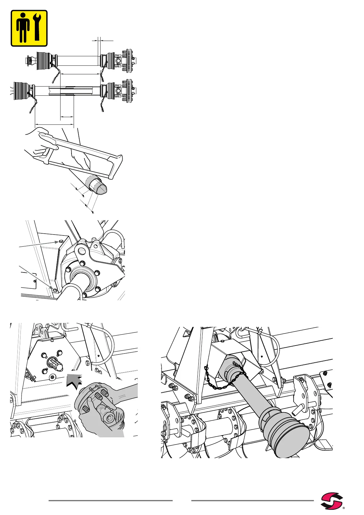
5.2 PTO DRIVE SHAFT COUPLING
Before installing the PTO drive shaft, the operator must:
• Read and understand the manual of the PTO drive shaft and of the tractor;
• Check that the number of revs. and the direction of rotation of the tractor
PTO correspond to those of the Tiller. If the direction of rotation of the Tiller
does not correspond to that of the tractor, contact the dealer or an authorised
workshop;
• Verify that the minimum and maximum length of the PTO drive shaft are those
required by the tiller-tractor coupling. Remember that when at maximum
extension, the pipes must overlap at least 1/3 of the length of the internal
pipe. Moreover, in the maximum closure position of the pipes, the minimum
clearance allowed of the plastic protections must be at least 2 cm. in order to
prevent damage to the protections and to the gear transmission. If this is not
the case, it must be shortened by cutting it as much as necessary; refer to
the PTO drive shaft use and maintenance manual or contact your authorised
dealer.
• Check that the PTO drive shaft protection is 100% intact, otherwise proceed
accordingly by consulting the relevant user manual.
To connect the PTO drive shaft, the operator must:
• Loosen and extract the screw located above the protection.
• Loosen the screws “B” located at the bottom of the protection.
• Remove the PTO protection by pulling it along the PTO axis to disengage the
open slots in which screws "B" are inserted.
• Direct the shaft correctly, so that the clutch is positioned from the side of the
equipment. In the event of joint without clutch, to position the shaft correctly,
refer to the gure of the tractor embossed on the external protection pipe.
• insert the PTO drive shaft hub onto the tiller PTO, making sure that the
clutch/PTO coupling is complete.
• Tighten the double bolt with two spanners.
• Insert the PTO drive shaft free hub onto the tractor PTO, holding the safety
pin pressed; releasing it only when the end of travel has been reached.
• Retract the PTO drive shaft until the pin engages in its seat with an audible
“click”.
• Reposition the PTO protection, correctly inserting the open slots on the
screws “B” and tighten the screw “A” and both screws “B”.
• Then hook the snap hooks of the retaining chains of the cardan shaft
protection to the tiller and tractor.
20
1/3L
L
L
=
=
A
B