- 22 -
Tiller CS
6. ADJUSTMENTS
6.1 CLUTCH ADJUSTMENT
The clutch, which is ttedon the coupling supplied with the Tiller, is sized to
transmit the correct power to the equipment and is calibrated and pre-set at
the factory; it is, therefore, inadvisable to modify this value in order to prevent
damage to the Tiller or to the PTO drive shaft.
WARNING!
SICMA shall not be liable for damage deriving from incorrect modication of the
clutch calibration.
However, adjustment becomes necessary if the clutch is triggered too frequently,
while operating on easily machinable soils, i.e. neither hard nor compact: this
means that the clutch calibration is too low.
The clutch associated to the PTO Drive Shaft is an FD1 EUROCARDAN, with
standard calibration of 900Nm. If it is necessary to increase its calibration, screw
the tightening nuts of the springs by 1/3 of a turn, thus obtaining an increase in
the transmissible torque of approximately 160 Nm. Unscrew the nuts if this value
needs to be reduced.
If you do not plan to use the equipment for a long period, it is advisable, after
noting the height of the springs measured with a precision gauge, to unscrew
the nuts compressing them to prevent the discs from “sticking” to each other and
causing them to seize.
When reusing the safety device, restore the original calibration by adjusting the
heights of the springs as follows:
• Screw the nuts by hand until the clearances of the springs are zero;
• Screw a nut precisely counting the number of revolutions necessary to reach
the original height of the compressed spring;
• Screw all the other bolts with the same number of revolutions used in the rst.
CAUTION!
Ensure that the height of the compressed springs is the same for all of them to
prevent clutch malfunction.
WARNING!
Do not pack the clutch springs together as the equipment would be unprotected
from overloads.
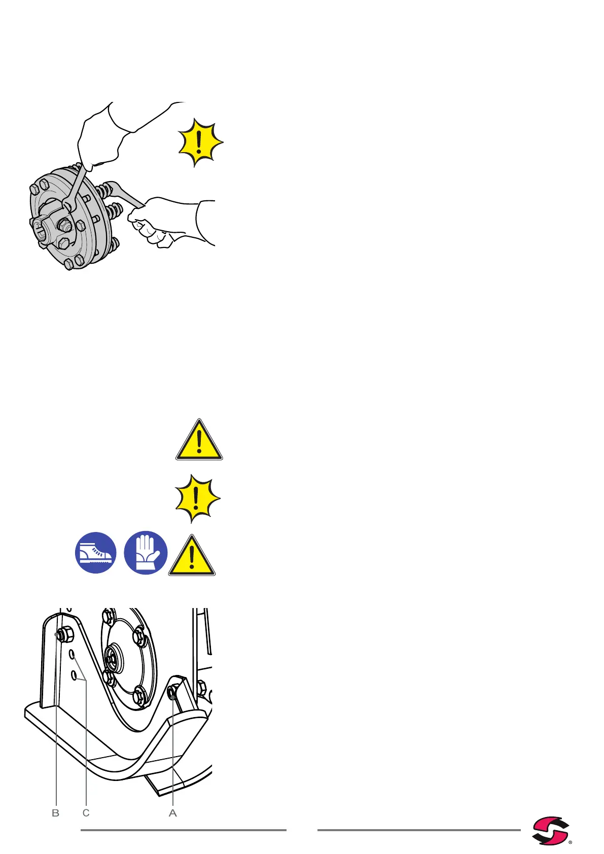
6.2 WORK HEIGHT ADJUSTMENT
The working height can be modied by altering the positions of the lateral skids.
CRUSHING HAZARD!
There are 2 adjustment options for skids, as well as the holes for locking them.
To modify the position of the skids, after having lifted the tiller and having
positioned it on supports, proceed as follows:
• Loosen bolt “A”.
• Loosen and remove bolt “B”.
• Reposition the slide engaging one of the two unused holes “C”.
• Replace and tighten bolt “B”.
• Tighten bolt “A”.
• Proceed with the same procedure on the opposite skid, making sure that
both are adjusted to the same height.
Finally, check that the Tiller is parallel to the ground and, if necessary, adjust its
planarity by using the lever on the tie-rod of the 3rd upper point (see sec. 5.1
).