Connector Pin Assignment
Note
The signals ERR0 and ERR1 transmit the status of the power supply unit to the connect-
ed drive amplifiers. These signals are generated by each power supply individually and
must not be connected between two power supply units. This also applies to the power
supply units of compact devices.
If several devices are connected in a system, the 24 V logic supply must be supplied to
one device from an external source. Then the logic supply is forwarded from that device
to the next and so on via X1 and X2 (see chapter 14 “System Connection”, page 154).
Related topics
X1, X2 – 24V, page 132
Hardware Status Signals ERR0/ERR1, page 166
Connection Diagram, page 186
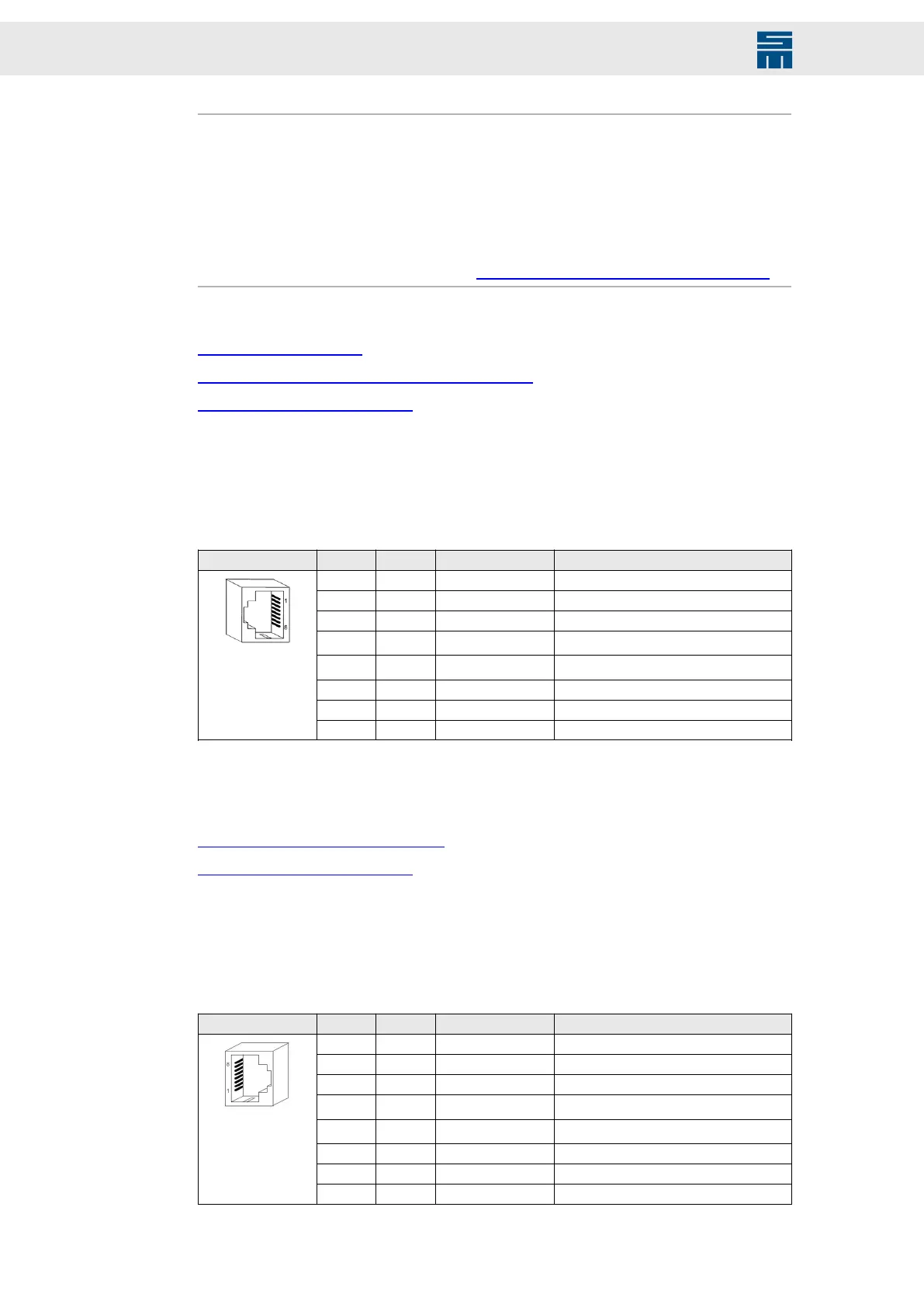
12.4 X3 – Bus Inputs (RS485,CAN)
RJ45
X3 Pin I/O Name Meaning
1 I SLI+ Data input of SERVOLINK 4
2 I SLI- Data input of SERVOLINK 4
3 I/O D+ RS485 interface
4 I/O
CAN_L
(1)
CAN_L
5 I/O
CAN_H
(1)
CAN_H
6 I/O D- RS485 interface
7 I/O GND Ground
8 I/O GND Ground
(1)
CAN bus is available with device version 9.100 and higher.
Related topics
X3, X4 – Bus Connection, page 132
Connection Diagram, page 186
12.5 X4 – Bus Outputs (RS485, CAN)
RJ45
X4 Pin I/O Name Meaning
1 O SLO+ Data output of SERVOLINK 4
2 O SLO- Data output of SERVOLINK 4
3 I/O D+ RS485 interface
4 I/O
CAN_L
(1)
CAN_L
5 I/O
CAN_H
(1)
CAN_H
6 I/O D- RS485 interface
7 I/O GND Ground
8 I/O GND Ground
108 Drive System SD2 - Hardware Description

 Loading...

