12.6.2 Digital Inputs / Outputs – HSPAM / VF
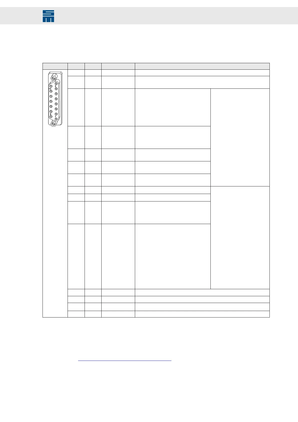
15-pole female submin D connector
X5 Pin I/O Name Configurable functions
1 I/O GND Logic supply
2 I IN0/ RON
▸
No function
▸
Switch on
3 I IN1/ STOP
▸
No function
▸
Quick stop type 5 (with slow down
ramp and controller off)
▸
Quick stop type 6 (with quick stop
ramp and controller off)
▸
Operation enable
▸
Operation enable with error reset
4 I IN2/ LIMIT-
▸
Operation enable
▸
Operation enable with error reset
▸
Internal target value Bit 3
▸
Parameter set Bit 0
5 I IN3/ LIMIT+
▸
Internal target value Bit 2
▸
Parameter set Bit 1
6 I IN4
▸
Internal target value Bit 1
▸
Parameter set Bit 2
7 I IN5
▸
Internal target value Bit 0
▸
Parameter set Bit 3
▸
No function
▸
Error reset
▸
External hardware OK
▸
Speed direction
▸
Teach no-load current
▸
MOP up
▸
MOP down
8 O OUT2
9 O OUT1
▸
Signal motor holding brake
10 O OUT0
▸
Ready type 1 (with power supply
okay)
▸
Ready type 2 (without power supply
okay)
11 O OUT3
▸
Signal motor holding brake
▸
No function
▸
M01 – Message power out-
put stage ready
▸
M02 – Message operation
enabled
▸
M03 – Message drive error
▸
M10 – Ref. value reached
▸
M11 – Torque reached
▸
M12 – Speed zero
▸
W04 – Power output stage
load
▸
W05 – Motor load
▸
W07 – Motor temperature
▸
W09 – Undervoltage power
output stage
▸
W12 – Speed error
▸
W24 – Warning threshold
’current'
▸
W26 – Warning threshold
’overload current'
12 - RIO− Controller OK (semiconductor relay max. 0.4 A / 60 V
AC
)
13 - RIO+ Controller OK (semiconductor relay max. 0.4 A / 60 V
AC
)
14 I
TEMP
(1)
Temperature sensor
15 O 24 V Logic voltage 24 V ±10 % (max. 0.25 A)
(1)
The temperature sensor is connected between GND and TEMP.
Locking bolts flange: max. tightening torque = 0.7 Nm
Related topics
X5 DIO – Digital Inputs/Outputs, page 134
111Drive System SD2 - Hardware Description
Connector Pin Assignment

 Loading...

