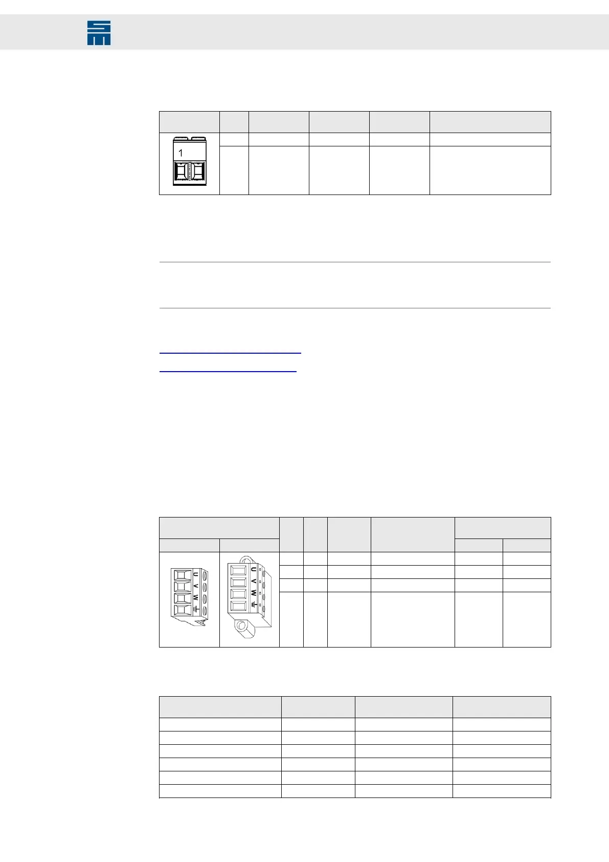
2-pole Power-Combicon connector, suitable for mating connector IPC 16/ 2-ST-10,16
(Phoenix)
Mating con-
nector X21
Pin Coding Name Position Meaning
1 - UB+ Right DC link +
2 Coded UB- Right DC link -
Specification of terminal connections:
▸
Conductor cross-section solid/stranded: 6 to –16 mm²
▸
Tightening torque: 1.7 to –1,8 Nm
Note
Consider that the conductor cross-section to be used for your application depends on
the total load of the power supply unit.
Related topics
Connection Diagram, page 186
System Connection, page 154
12.17 X22, X24, X47 – Motor Connection
4-pole Power-Combicon connector
▸
X22: suitable for mating connector PC 4/ 4-ST-7,62 (Phoenix)
▸
X24: suitable for mating connector IPC 16/ 4-ST-10,16 (Phoenix)
▸
X47: suitable for mating connector IPC 16/ 4-STF-10,16 (Phoenix)
Mating connector Coding of
compact devices
X22 / X24 X47
Pin I/O Name Meaning
X22A X22B
1 O U Motor phase U – –
2 O V Motor phase V Coded –
3 O W Motor phase W – Coded
4 PE Protective conductor – –
The following table specifies the terminal connections according to the device variant
and the connector:
03621.. Connector Conductor cross-sec-
tion (solid/stranded)
Tightening torque
..10DDC / DDF / EEF X22A, X22B 1.5 to 4 mm² 0.5 to 0.6 Nm
..10EEC X22A, X22B 2.5 to 4 mm² 0.5 to 0.6 Nm
..11DC / DF / EF X24 1.5 to 16 mm² 1.7 to 1.8 Nm
..11EC / IF X24 2.5 to 16 mm² 1.7 to 1.8 Nm
..11IC X24 6 to 16 mm² 1.7 to 1.8 Nm
..11MF / NF X24 10 to 16 mm² 1.7 to 1.8 Nm
119Drive System SD2 - Hardware Description
Connector Pin Assignment

 Loading...

