12.22 X68 – DC Link Connectors
DANGER
High voltages in the intermediate circuit
Note that even after the power supply unit has been switched off high volt-
ages may occur in the intermediate circuit of the complete system that can
cause serious injuries.
→ Wait until the intermediate circuit is fully discharged before cutting the
connections of the intermediate circuit ("capacitor discharge").
→ Take the following steps before working on the device or on the inter-
mediate circuit:
→ Disconnect the power supply unit definitely from the mains supply.
→ Wait until the discharge time of the of the DC link capacities has ex-
pired. It is longer than 4 minutes.
→ Ensure by measuring that the intermediate circuit is fully discharged.
→ Disconnect the intermediate circuit connections from the power sup-
ply.
→ Also consider general safety instructions before you continue working
on the device.
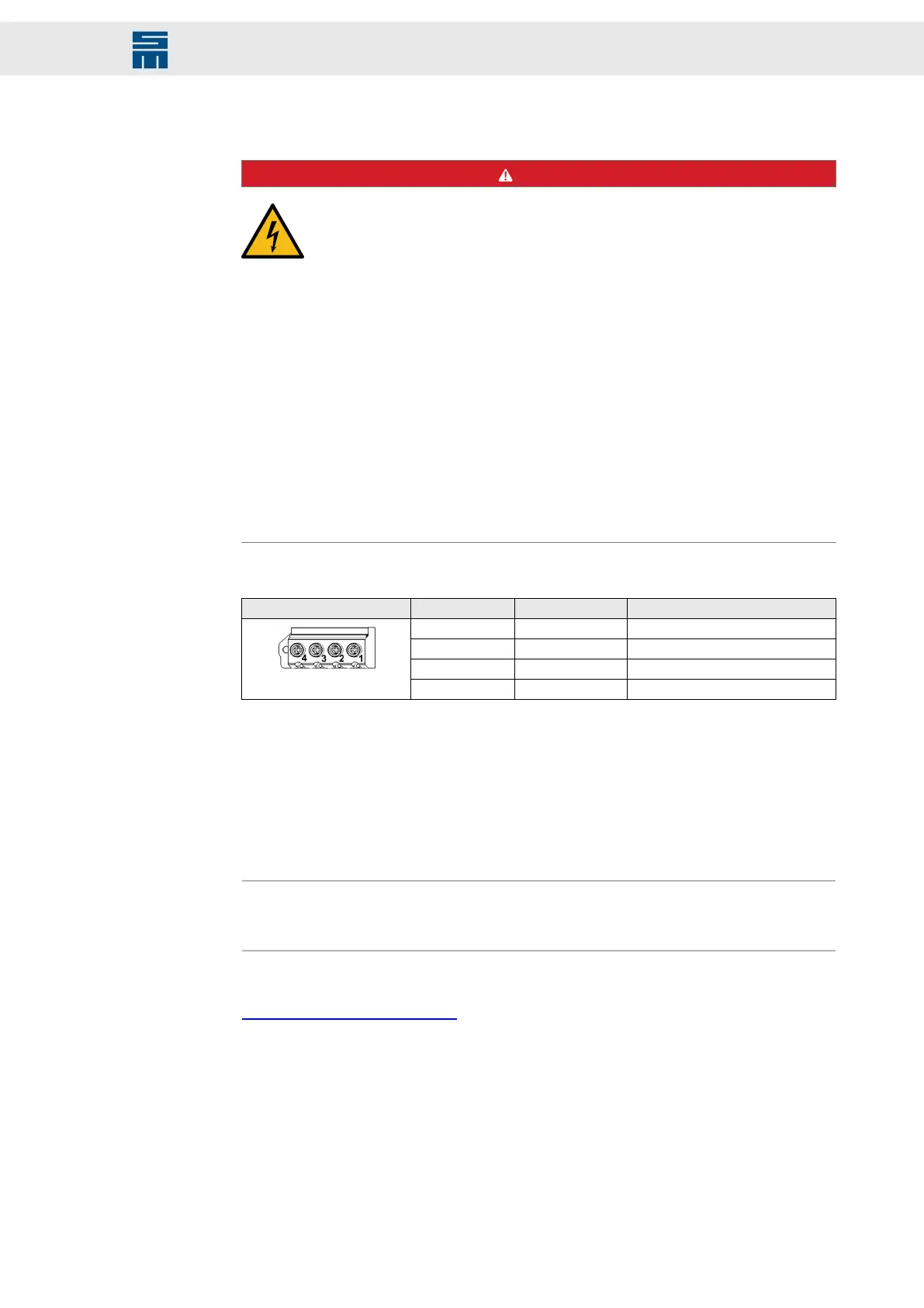
4-pole screw terminal (Weidmüller)
X68 Pin Name Meaning
1 UB+ DC link voltage +
2 UB+ DC link voltage +
3 UB- DC link voltage
4 UB- DC link voltage
Specification of terminal connections:
▸
Conductor cross-section: min. AWG 20 - max. AWG 1
▸
Conductor cross-section solid: 0.5 - 16 mm²
▸
Conductor cross-section stranded: 6 - 50 mm²
▸
Stripping length of the conductors: 18 mm
▸
Tightening torque: 4 Nm
Note
Consider that the conductor cross-section to be used for your application depends on
the total load of the power supply unit.
Related topics
Connection Diagram, page 186
125Drive System SD2 - Hardware Description
Connector Pin Assignment

 Loading...

