Connection Examples
13 Connection Examples
The following sections provide connection examples for the individual connectors of the
device.
Wiring examples for the device connection can be found in the Appendix.
13.1 X1, X2 – 24V
Fig. 81: Logic voltage: 24 V ±20 %
Fig. 81: Logic voltage: 24 V ±20 %
Note
If the device is a power supply unit or a drive amplifier with integrated power supply, the
signals ERR0 and ERR1 are outputs. For all other drive amplifiers these signals are in-
puts and provide for better error response (see pin assignment).
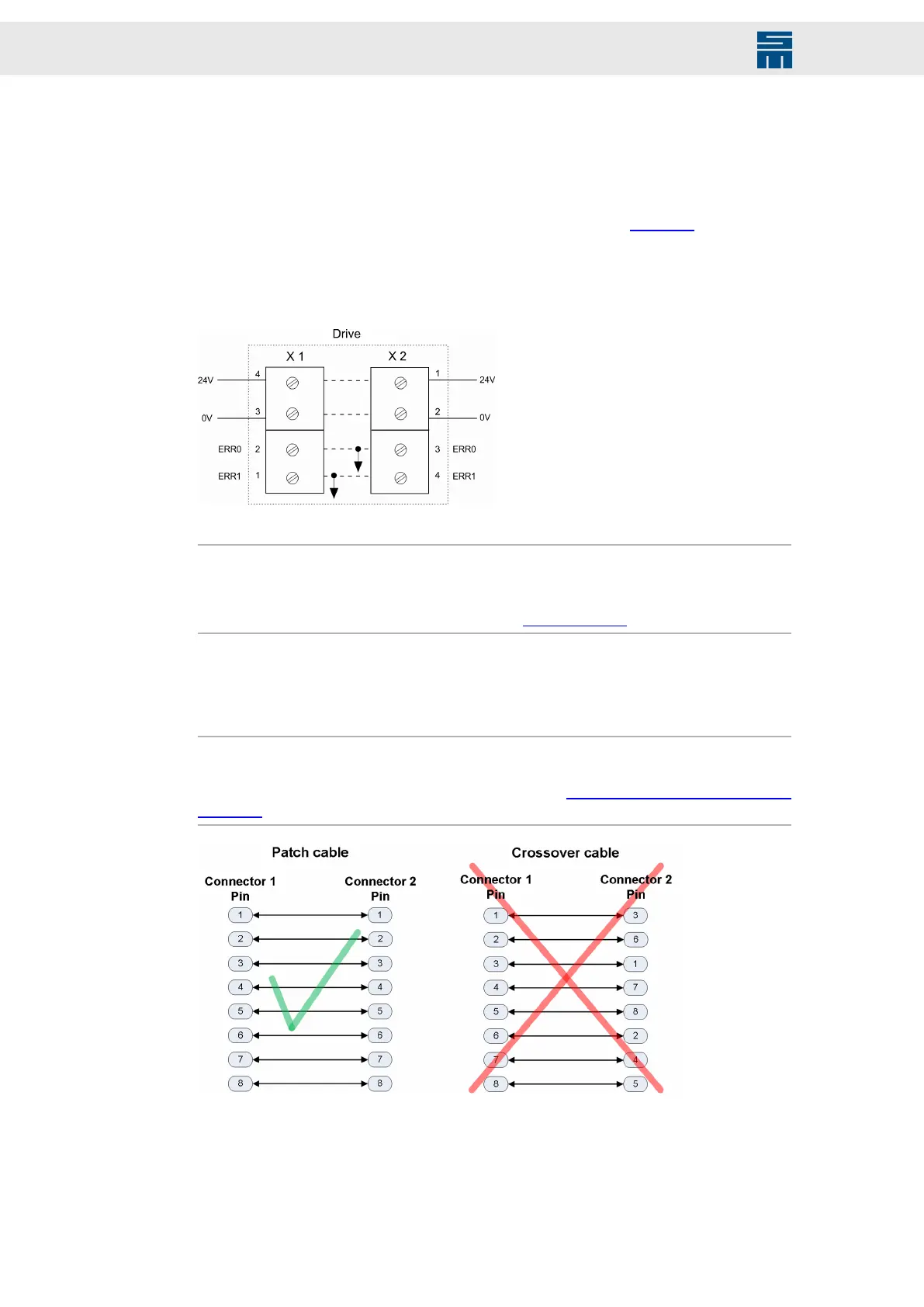
13.2 X3, X4 – Bus Connection
Note
To interconnect the devices, for example via the RS485 bus, you can use ready-made
Ethernet patch cables (no crossover cables), see also chapter 14 “System Connection”,
page 154 (connection C).
Fig. 82: Faulty bus connection
Fig. 82: Faulty bus connection
132 Drive System SD2 - Hardware Description

 Loading...

