System Connection
14 System Connection
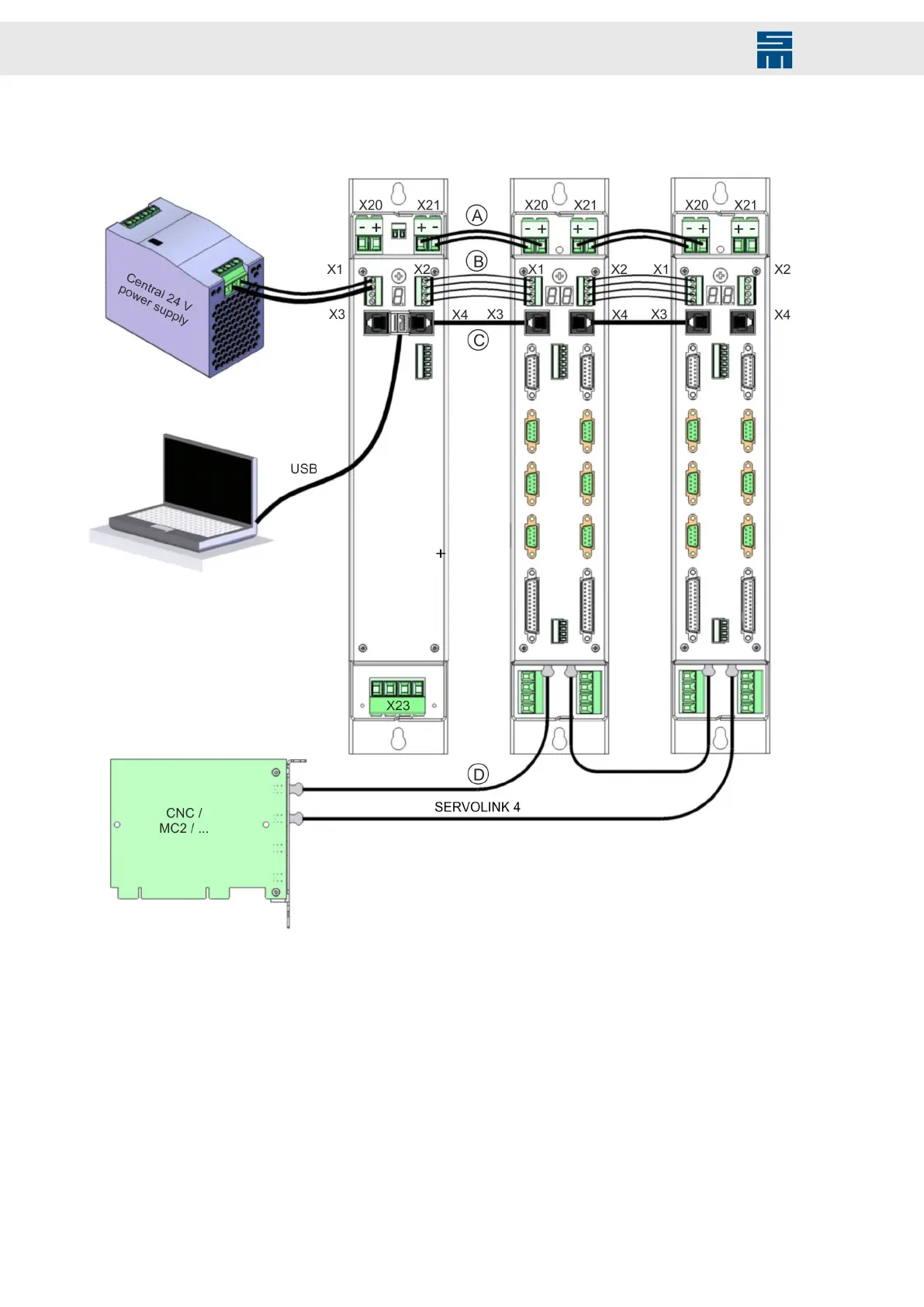
Fig. 93: Connection of PS2 and SD2
Fig. 93: Connection of PS2 and SD2
[A] DC intermediate circuit supply UB+, UB-
[B] Logic bus with 24 V logic voltage
[C] RS485 interface for diagnosis and parameterization
[D] SERVOLINK 4 control bus
The power supply unit allows communication between the PC and the connected dri-
ve amplifiers. The CNC and the power electronics (SD2) communicate via a serial bus,
SERVOLINK 4
154 Drive System SD2 - Hardware Description

 Loading...

