Connector Pin Assignment
Remove device cover: delivery from July 2019 onwards
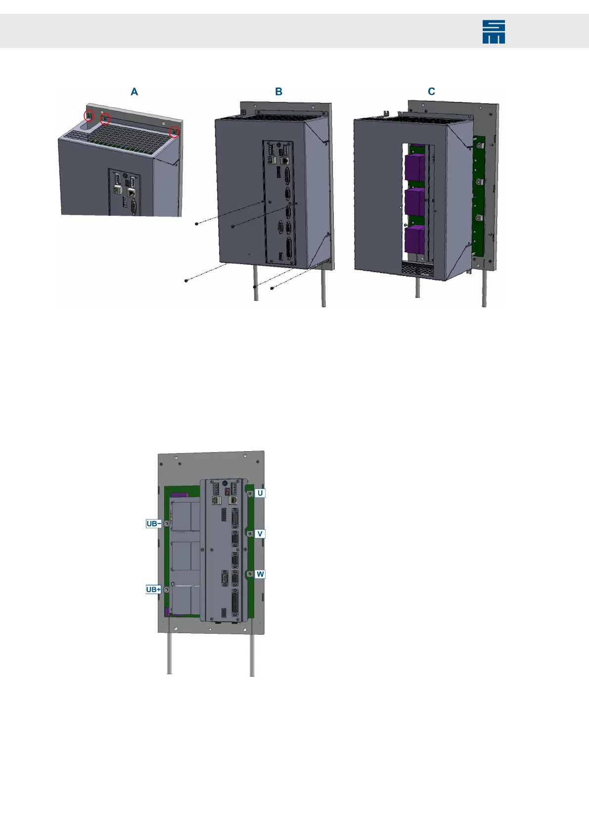
➮ Loosen the 3 screws (lens head screws M3×6, DIN 7985, zinc coated, Torx) of the
device cover somewhat but do not remove them [picture A].
➮ Remove the other 5 screws (lens head screws M3×6, DIN 7985, zinc coated, Torx)
of the device cover [picture B].
➮ Slide the device cover a little downwards and then remove it from the device
[picture C].
➮ You find the connectors for the DC link (UB+, UB−) and the motor (U, V, W) on the
left and on the right side of the device as shown below. They are implemented as
individual power bushes.
128 Drive System SD2 - Hardware Description
 Loading...


