Connection
6.2 Electrical connection
Synchronous/induction motors 1PH813
Operating Instructions, 04/2009, 610.48000.22
41
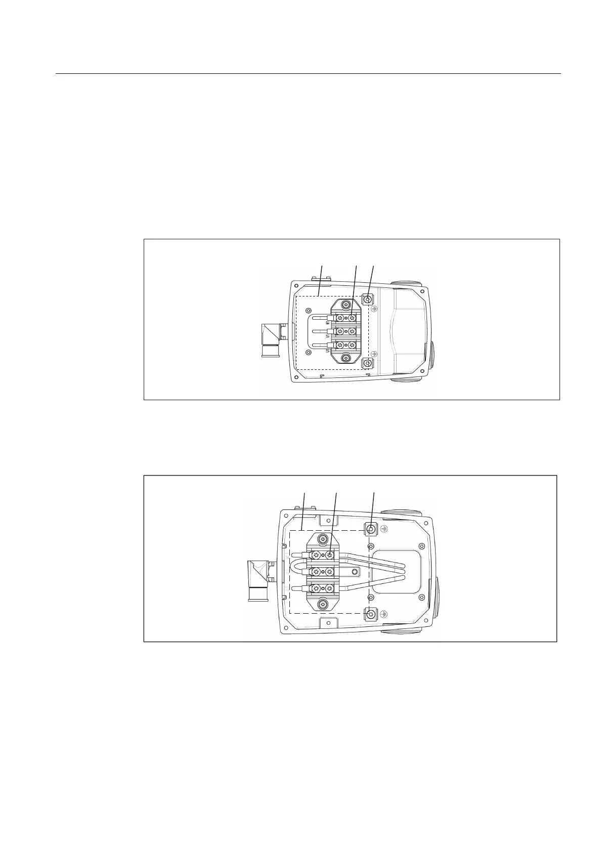
6.2.4 Terminal box
● Assign the terminals in the terminal box as shown in the diagrams "Terminal box: 3-pole"
and "Terminal box: 6-pole".
● Connect the protective conductor.
● Use cable lugs to DIN 46234.
● Do not remove the insulation strips.
● Screw the lid of the terminal box back on (tightening torque: 5 Nm).
1 Terminal screw M6
2 Grounding screw M6
3 Insulation strips
Figure 6-2 Terminal box gk833, 3-pole
1 Terminal screw M6
2 Grounding screw M6
3 Insulation strips
Figure 6-3 Terminal box gk843