Connection
6.2 Electrical connection
Synchronous/induction motors 1PH813
46 Operating Instructions, 04/2009, 610.48000.22
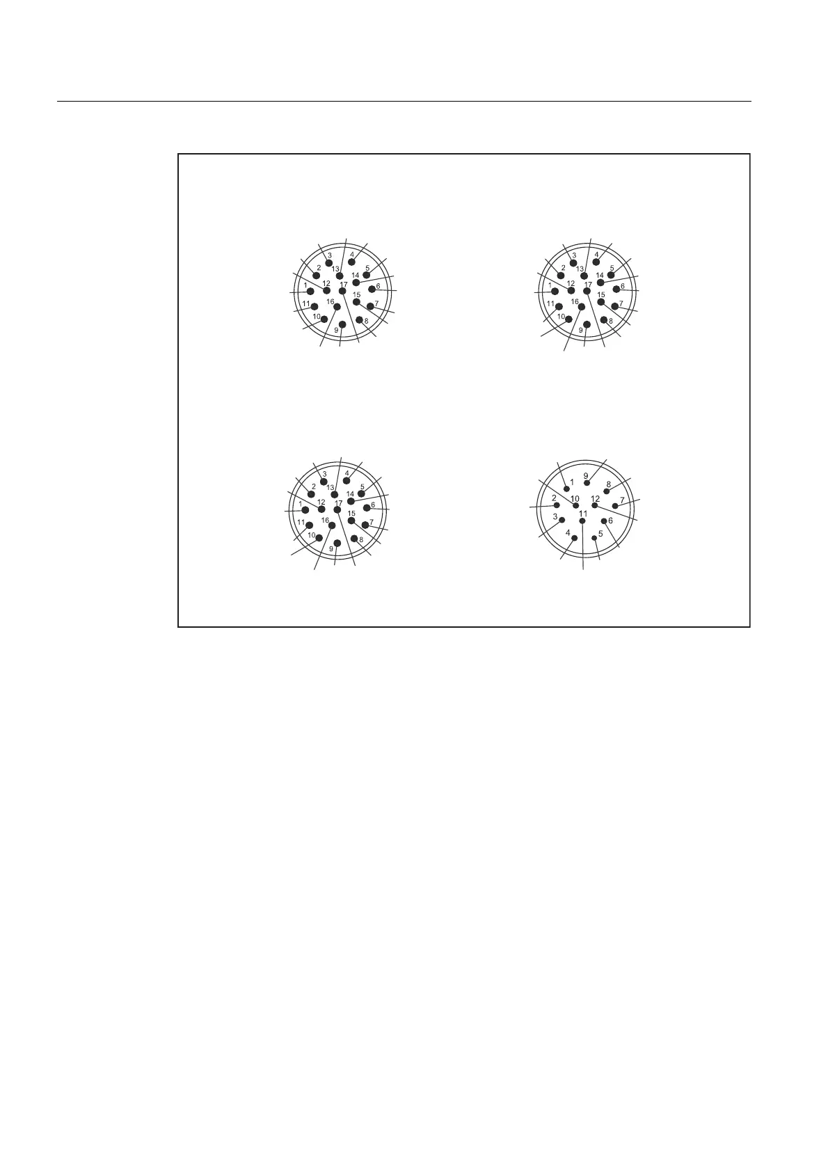
,QFUHPHQWDOHQFRGHU+7/65
$EVROXWHHQFRGHU(Q'DW65
,QFUHPHQWDOHQFRGHU
VLQFRV9SS
$
%
$
5
$
GDWD
%
%
%
$
5
5
$
%
$
'
&
5
0(QFRGHU
'
06HQVH
5
5
QRW
FRQQHFWHG
&
36HQVH
3(QFRGHU
%
QRWFRQQHFWHG
QRW
FRQQHFWHG
FORFN
QRWFRQQHFWHG
0(QFRGHU
5
FORFN
06HQVH
5
36HQVH
3(QFRGHU
GDWD
5
5
&75/
3(QFRGHU
QRWFRQQHFWHG
0(QFRGHU
$
%
5
$
5
0(QFRGHU
06HQVH
5
5
36HQVH
3(QFRGHU
%
QRWFRQQHFWHG
QRWFRQQHFWHG
QRWFRQQHFWHG
QRWFRQQHFWHG
QRWFRQQHFWHG
,QFUHPHQWDOHQFRGHU
VLQFRV9SS65
Figure 6-10 Signal connection (view of connector pins)
A suitable socket connector can be used to rotate the angle plug. Make sure that the socket
connector is completely secure to avoid damaging the pin contacts.
6.2.9 Connecting the temperature sensor
The temperature sensor is connected to the signal connector together with the speed
encoder signal.