Connection
6.2 Electrical connection
Synchronous/induction motors 1PH813
48 Operating Instructions, 04/2009, 610.48000.22
6.2.11 Connecting the separately-driven fan
The fan connection is located in the fan terminal box.
Table 6- 5 Connection specifications for separately-driven fans (1PH813x)
Max. current consumption at:
Air flow direction
400 V / 50 Hz (±10 %) 480 V / 60 Hz (+5 %/-10 %)
DE → NDE 0.46 A 0.53 A
NDE → DE 0.30 A 0.35 A
Note the following information regarding connections:
● Only use cables that comply with the relevant installation regulations regarding voltage,
current, insulation material, and load-carrying capacity.
● Before connecting the device, make sure that the line voltage matches the device
voltage.
● Check whether the data on the fan rating plate matches the connection data.
● Open the terminal box and route the cables (not supplied) into the terminal box.
● Connection cables must not be subject to excessive tensile stress.
● Connect the protective conductor (PE).
● Connect the other cables to the relevant terminals (refer to the connection diagrams).
NOTICE
To protect the device against moisture, make sure that you use suitable cables at the
connection cable gland on the terminal box and that the lid for the terminal box is
properly fitted. Water must not be allowed to run along the cables and into the terminal
box.
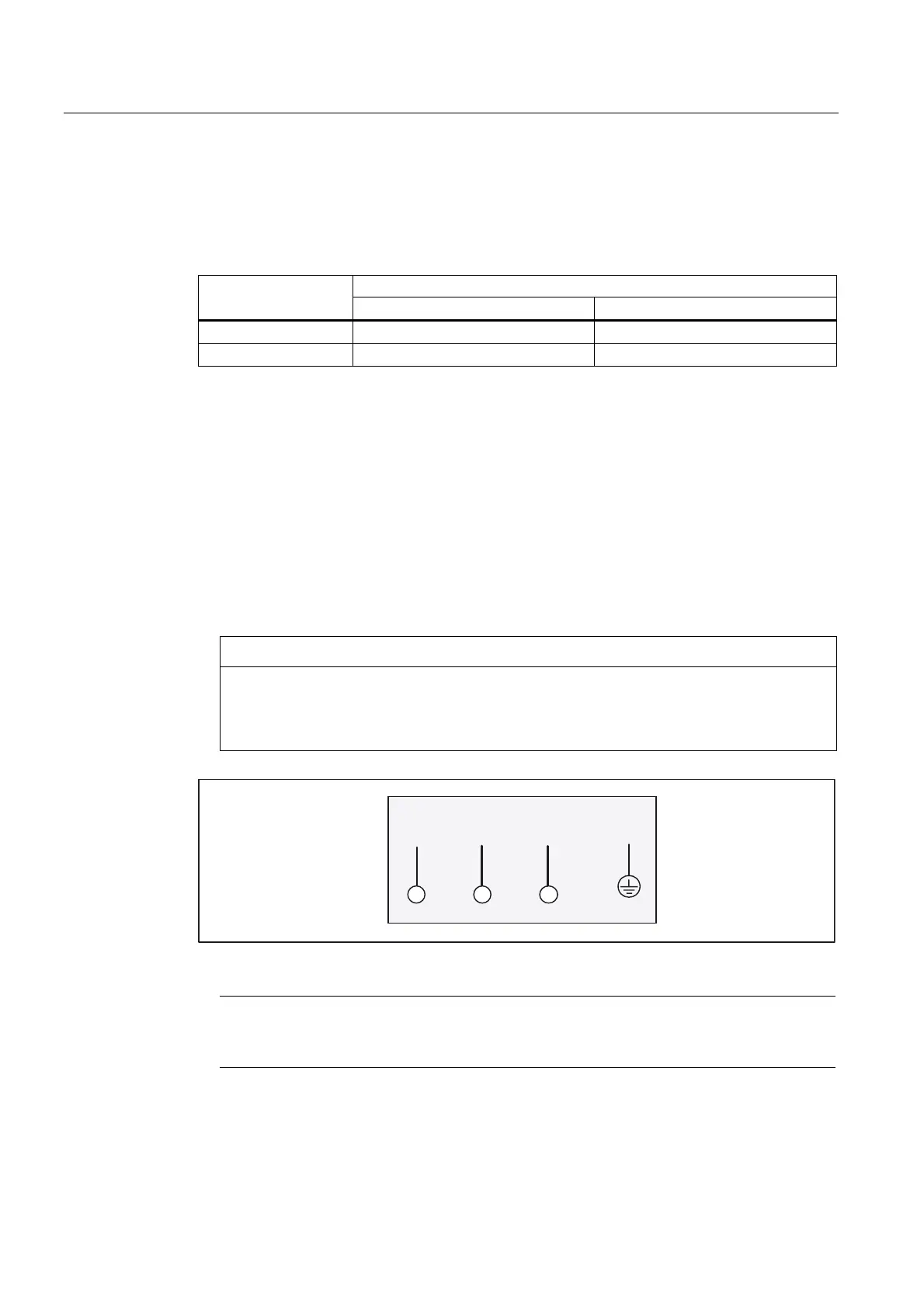
:8 9 3(
Figure 6-12 Connection for the separately-driven fan in the terminal box
Note
If you order the motor with a power connector, the separately-driven fan is connected with
a size 1 power connector.