Connection
6.2 Electrical connection
Synchronous/induction motors 1PH813
40 Operating Instructions, 04/2009, 610.48000.22
Table 6- 3 Derating factors for power and signal cables
Ambient air temperature [°C] Derating factor to EN 60204-1, table D1
30 1.15
35 1.08
40 1.00
45 0.91
50 0.82
55 0.71
60 0.58
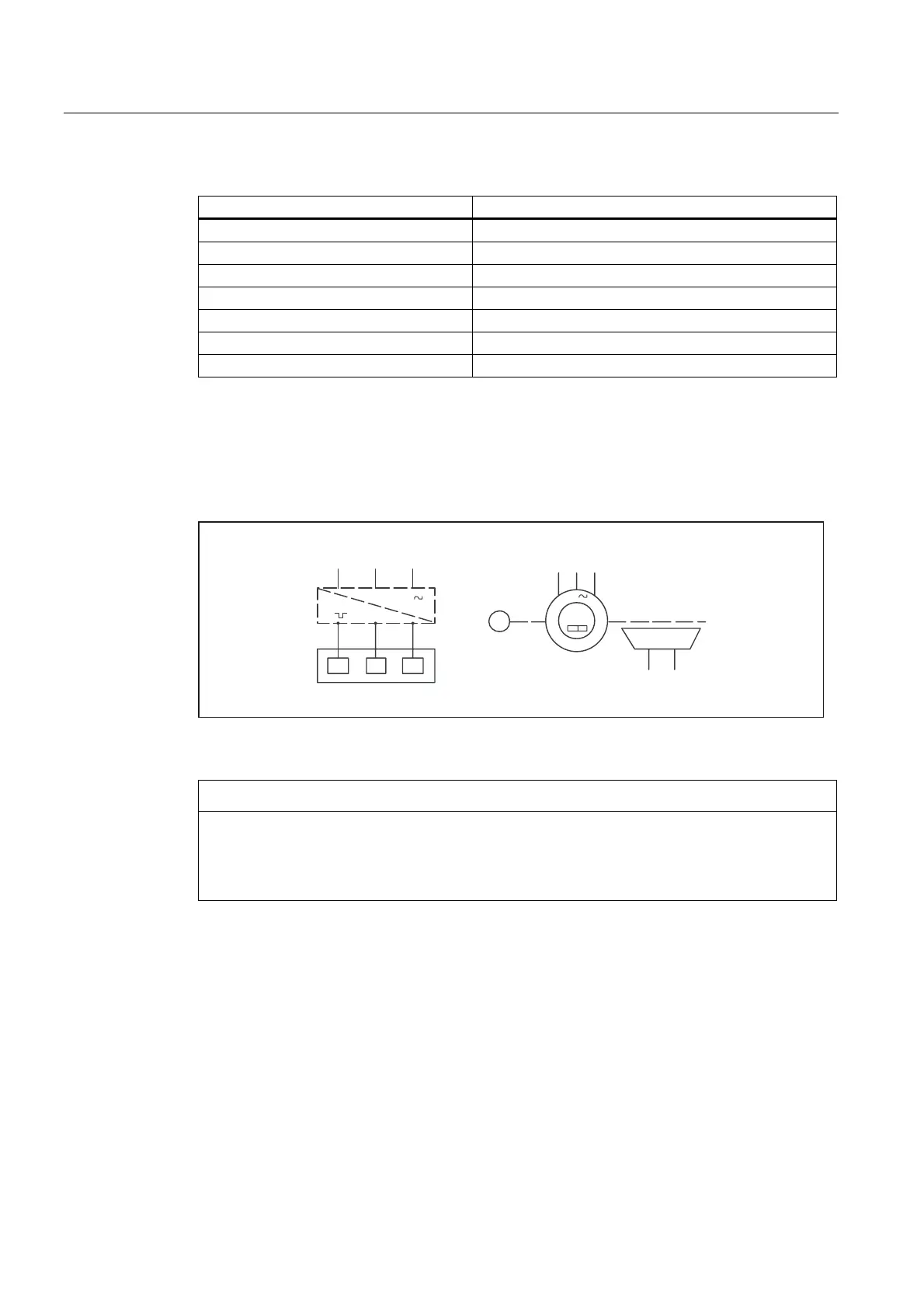
6.2.3 Circuit diagram
The circuit diagram contains information about wiring and connecting the motor winding. The
circuit diagram can be found on the lid of the terminal box.
// /
89:
8 9 :
6XSSO\
0RWRU
(QFRGHU
89:
0
0RWRU
%UDNH
%'
%'
Figure 6-1 Circuit diagram
NOTICE
Cable outlet direction
If the direction of the cable outlet is not changed correctly, this can damage the connecting
cables. The direction of the cable outlet must not be changed since this renders all warranty
claims invalid.