Maintenance
9.2 Repair
Synchronous/induction motors 1PH813
Operating Instructions, 04/2009, 610.48000.22
73
Removal
1. Unscrew the screw (1).
2. Remove the connector cover (2).
3. Remove the connector with signal cable.
4. Unscrew the screws (9.07) for the torque bracket.
5. Unscrew the encoder screw (9.05) (make sure that the motor rotor does not also start to
rotate).
6. Remove the encoder from the motor shaft:
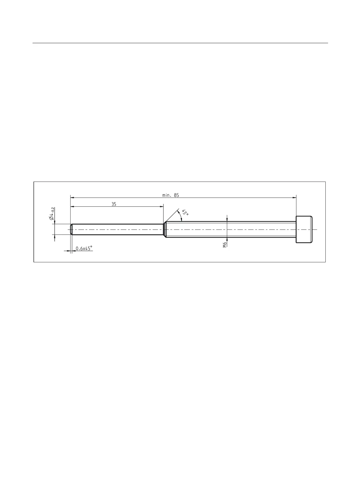
– You can remove the encoder directly by inserting a special screw (see diagram).
– If a special screw is not available, you can remove the encoder by inserting a threaded
pin (e.g. DIN 913 M5 x 30) into the end of the motor shaft to protect the centering hole
thread and then inserting a screw M6 x min. 40.
Figure 9-3 Special screw
Installation
1. Screw the torque bracket (9.06) onto the encoder by means of screws (7) and secure
(e.g. with Loctite 243). Note the distance between the torque bracket and encoder (this
step does not need to be carried out if the encoder is already mounted).
2. If necessary, remove the threaded pin (used earlier to remove the encoder).
3. Unscrew the screw (1) for the replacement encoder.
4. Remove the connector cover (2) for the replacement encoder. Place the encoder (with
torque bracket) (9.06) onto the cone of the motor rotor and screw in the encoder screw
(9.05) (tightening torque 5
-1
Nm). Make sure that the motor rotor does not also start to
rotate.
5. Secure the torque bracket (9.06) by means of screws (9.07) on the bearing shield (6.01)
(note the radial deflection of the encoder).
6. Press on the metal sleeve for the connector cable.