Compact Operating Instructions in accordance with EN 61010-1 and EN 60079-0
14 A5E45779144002-01, 09/2018
Connection of the signal lines
The 24 V/1 A power supply must be a power-limited safety extra-low voltage with safe electrical isolation (SELV).
Only connect the signal lines to devices which also have reliable electric isolation from their power supply.
● The connection lines to the relay outputs, binary inputs, and analog outputs must be shielded.
● The analog outputs are floating, but have a common negative pole.
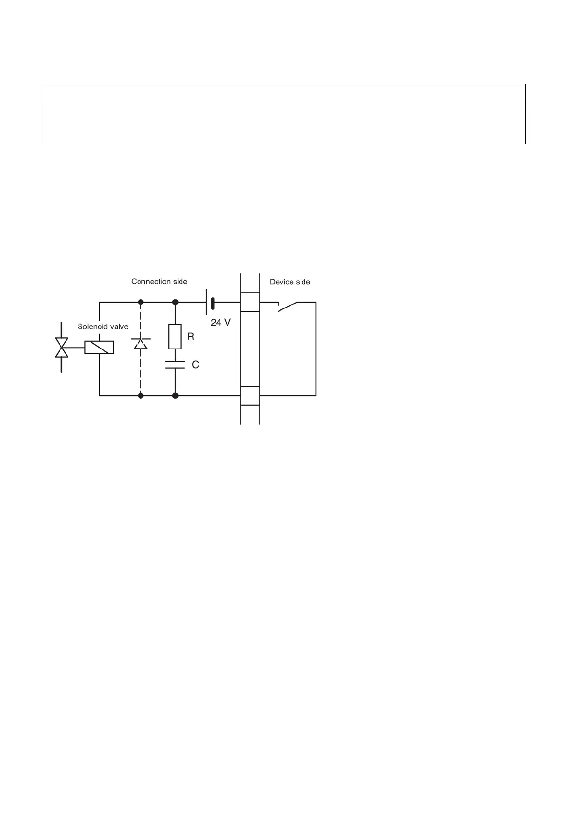
● As a measure to suppress sparking across the relay contacts (e.g. limit relays), RC elements must be connected as
shown in the following figure. Note that the RC element results in a drop-out delay for an inductive component (e.g.
solenoid valve). The RC element should be sized according to the following rule of thumb:
– R = R
L
/2; C = 4L/R
2
L
,
where R = 100 Ω and C = 200 nF are sufficient.
– You must use a non-polarized capacitor for the RC element.
Figure 4-1 Measure to suppress sparks on a relay contact
When operated with direct current, a spark suppression diode can be installed instead of the RC element.
Please also observe the following for correct operation:
● Connect the analyzer's enclosure to the equipotential bonding.
● Identify the intrinsically-safe lines and route them separately from the non-intrinsically-safe lines. Observe the minimum
distances required when doing this.
● Connect the signal lines to the Sub-D plugs at the rear of the device.
Refer to the ELAN interface description (Order No. C79000-B5200-C176 German, C79000-B5276-C176 English) for details
on the interface cable.
 Loading...