33
nection. When you have completed the function test, exit by pressing
"ESC" and return to normal operating mode.
8 Setting Parameters at the device
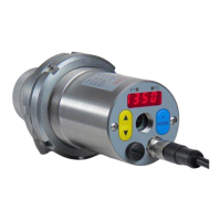
In addition to the configuration possibilities described in Chapter 7, many
parameters can be adjusted at the rear panel using push buttons. These
settings can be accessed via configuration layers.
8.1 Configuration layers
The configuration layers are structured as follows:
C001 Temperature measurement via spectral channel 1
C010 I/O Configuration
C011 General functions
C020 Display temperature readings
C100 Simulated current signal for outputs Ao1 and Ao2
The following chart lists all parameters. Certain parameters will be sup-
pressed at the rear panel display if the prerequisite function is deactivat-
ed. For example: the smoothing time cannot be configured when signal
smoothing is not activated.
Temperature measurement via spectral channel 1 (configuration
layer: C001)
The reflected thermal radiation from the sur-
roundings as a portion of the total IR radiation
collected by the sensor in %