18 Installing the WLAN Expansion
DRAFT 22.04.2008
ARCADIS SP00-000.814.09.01.02 Siemens
11.07 CS PS SP
Page 18 of 78
Medical Solutions
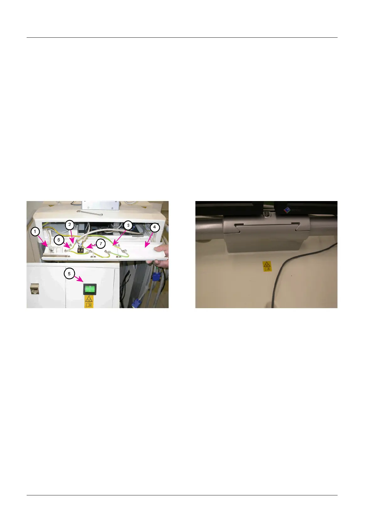
• Plug in the S15.1 cable on the power switch (5/Fig.8/p.17).
• Plug in the S15.2 cable on the power switch (6/Fig.8/p.17).
• Cut open the heat-shrink tubing around the power cable and the trailing attached
ground wire and remove it.
• Connect the ground wire to the connection terminal.
• Connect the attached power connector on the power cable to the existing power outlet
strip.
Laying out the Ground Wiring at the Connection Terminal
• Lay out the grounding wires at the connection terminal as shown in (Fig.7/p.17).
When doing this, also secure the ground wire connections for the new power cables.
See (6/Fig.7/p.17) and (7/Fig.7/p.17).
¹ Make sure that the ground wire connection coming from the monitor carriage is
securely connected.
¹ Make sure that all ground wire connections have good contact.
Labels with the Reference Symbol to the Operator Manual
• Attach one of the labels with the warning symbol for non-ionizing radiation and a refer-
ence symbol to to the Operator Manual along side one another, below the WLAN power
switch.
• Attach the 2nd label with the warning symbol for non-ionizing radiation and the 2nd ref-
erence symbol to the Operator Manual on the top console of the monitor carriage, cen-
tered between the base of the monitor base and the inset to store the mouse (= location
of the signal source below the console, centered to the signal antennas of the WLAN
Client).
Fig. 9: Connection terminal, already installed
Pos. 1 Cover panel with RJ45 network sockets
Pos. 2 Cover panel for WLAN power switch
Pos. 3 Blank cover panel, short
Pos. 4 Blank cover panel, long
Pos. 5 Illustration of the power switch installation location
Pos. 6 Power cable ground wire to power outlet strip
Pos. 7 Power cable ground wire to the WLAN power supply
Fig. 10: Label with reference to the User Manual
 Loading...