System installation
18
Siemens AG 03.2011
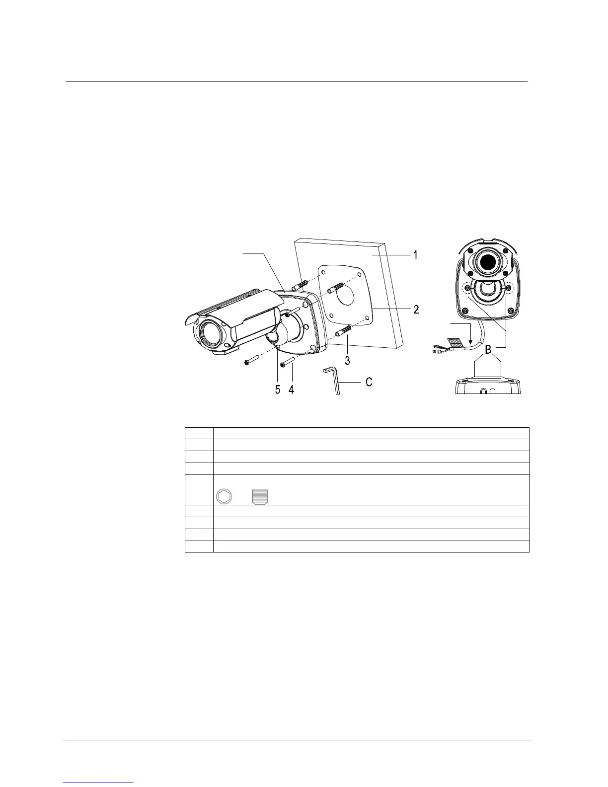
7.2.2 Installation 2 (mounting base)
1. Drill the mounting holes using the drilling template (or the bottom of the
mounting base).
2. Insert the plastic anchors into the holes.
3. Punch out the cable entry hole in the mounting base.
4. Connect BNC cable and the communication lines.
5. Align the plastic anchors with the holes in the mounting base.
6. Insert the torx screws (T-20) and tighten them.
7. Adjust the camera as required using the pan & tilt function. Tighten the grub
screw and the two torx screws to lock the camera in position.
6
A
Fig. 7 Installation 2
1 Wall
2 Template
3 Plastic anchor Ø 8x40 mm (4x)
4 Torx screw T-20, 6x35 mm (4x)
5 Cap-head screw (grub screw) M5x5 mm
6 Mounting base
A Connection cable
B Torx screw T-20
C Allen key 2.5 mm
 Loading...