Connection
22
Siemens AG 03.2011
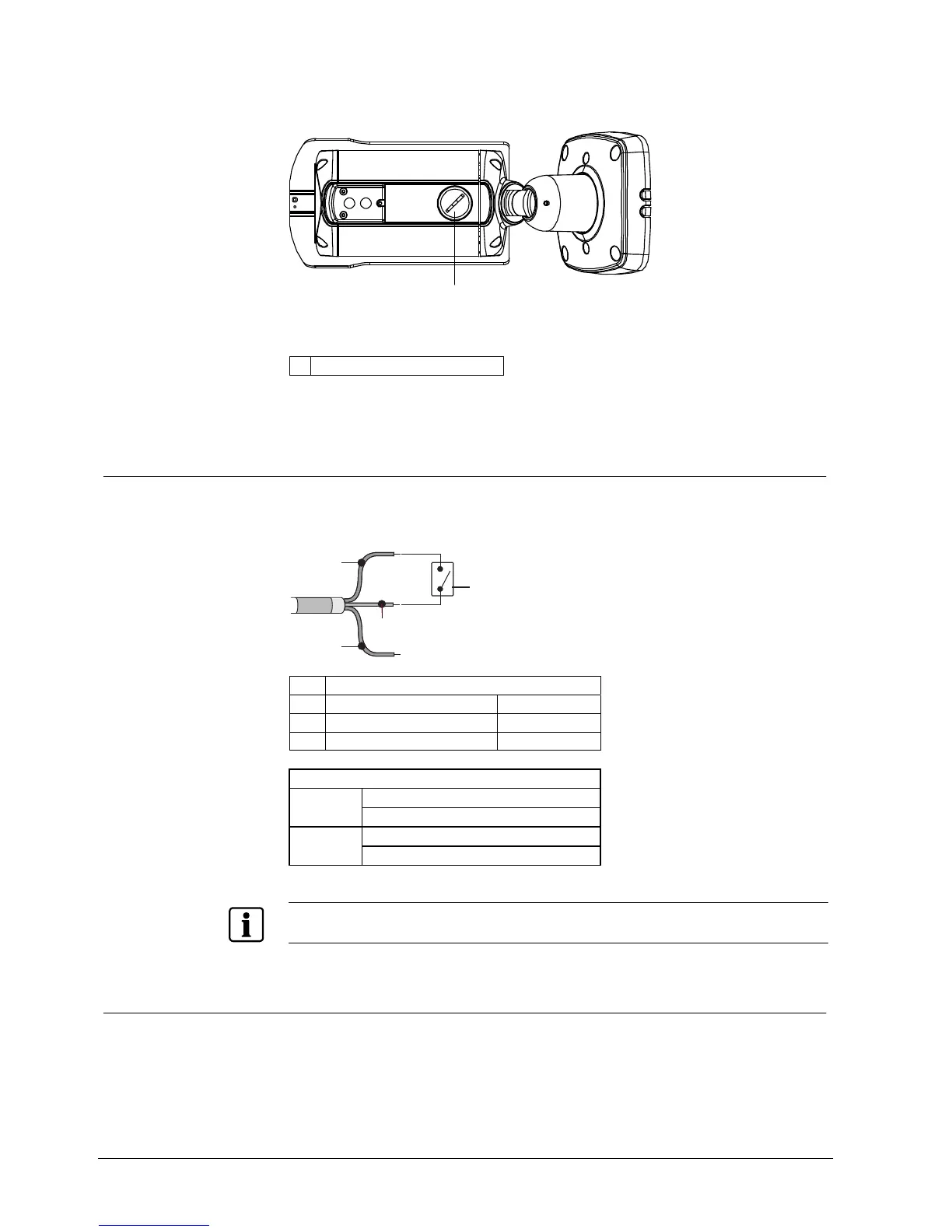
TP output selector switch location
After removal of the flat-head cap the DIP switch is visible.
1
Fig. 11 Bottom view of the camera
1 Flat-head cap
8.1 General
8.1.1 Automatic switching between colour and B/W mode
The camera must be connected to an external sensor to receive day/night
detection signals.
2
3
4
1
1 External sensor switch
2 External input (EXT-In) Grey
3 External output (EXT-Out) White-Black
4 GND Black
Positions of the external sensor switch (1)
Activate alarm: closed
EXT-IN
Deactivate alarm: open
Alarm activated: 5 V
EXT-OUT
Alarm deactivated: 0 V
To activate the sensor inputs, select the mode EXT in the function menu B/W.
8.1.2 RS-485 connection
The camera can be controlled remotely by an external device or control system,
such as a control keyboard, using RS-485 half-duplex. Connect marked Rx+, Rx-
to Tx+ and Tx- of the RS-485 control system.
 Loading...