Connection
21
Siemens AG 03.2011
8 Connection
CAUTION
Do not connect the camera to the power supply until all other connections have
been completed. Any unused wires should be trimmed and insulated.
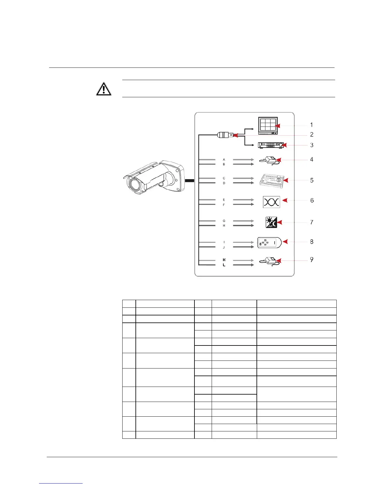
Fig. 10 Connection
1 Monitor BNC
2 Video BNC
3 DVR/VCR BNC
A Red +12 V DC / 24 V AC 4 Power supply of the
camera
B White - 12 V DC / 24 V AC
C Blue RS-485(-) 5 RS-485 connection
D Green RS-485(+)
E Yellow TP-A(+) 6 Twisted-pair video output
F Green/White TP-B (-)
G Grey Ext. input 7 Aut. switching between
colour and B/W
Alarm input
H White/Black Ext. output
I Black 8 Remote control
J Blue/White
GND
Control
K Pink Heater (AC 24 V) 9 Heater power, operating
temperature -30°C
L Brown Heater (AC 24 V)
Orange/Black TxD RS-232 connection,
PC configuration
Orange RxD
MD output Violet MD/FD off: 0 V, on: 3.3 V
 Loading...