Setting functions
8.3 Setpoints
Inverter with CU230P-2 Control Units
Operating Instructions, 11/2013, FW V4.6.6, A5E02430659B AG
243
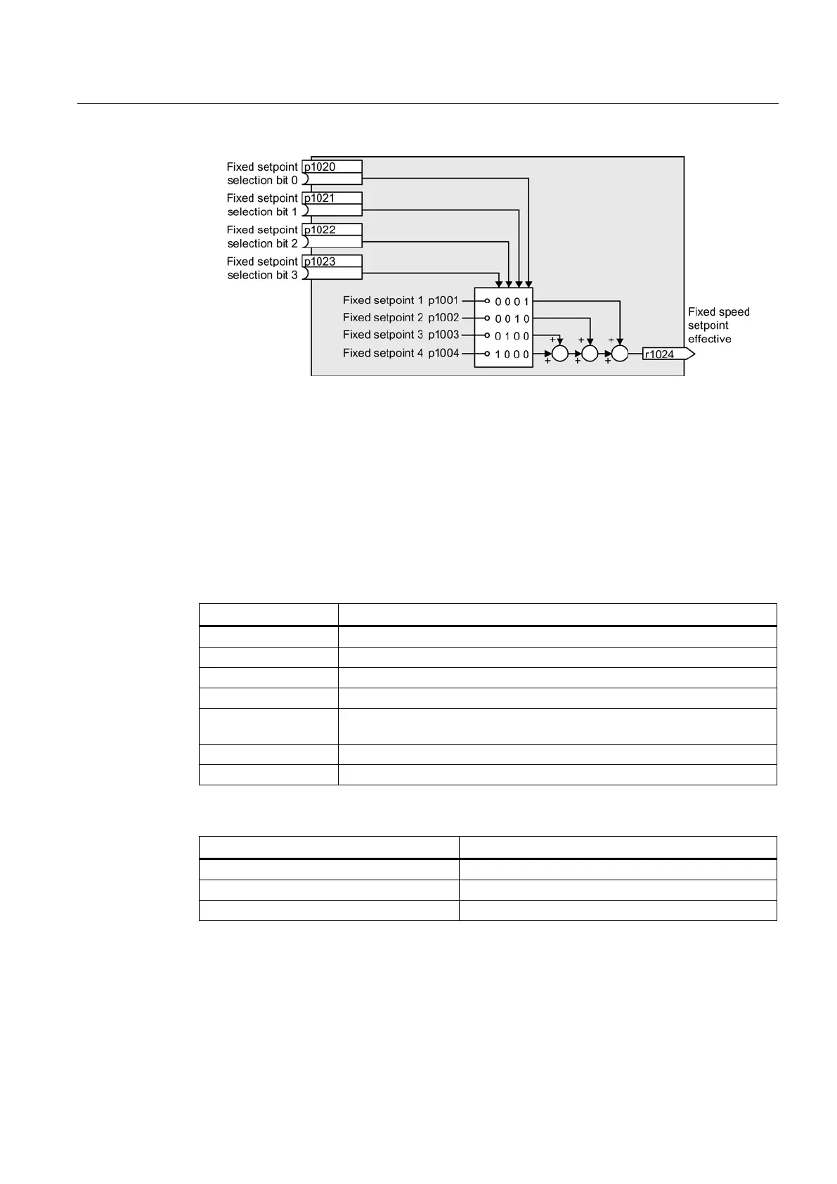
Figure 8-17 Simplified function diagram for directly selecting fixed setpoints
Example: Select two fixed setpoints directly
The motor should operate at different speeds as follows:
● The signal on digital input 0 switches the motor on and accelerates it to 300 rpm.
● The signal at digital input 1 accelerates the motor to 2000 rpm.
● The signals at the two digital inputs accelerate the motor to 2300 rpm.
Table 8- 13 Settings for the example
Fixed speed setpoint 1 [rpm]
Fixed speed setpoint 2 [rpm]
ON/OFF1: Switch on motor with digital input 0
Main setpoint: Interconnect the main setpoint with the fixed speed setpoint.
p1020 = 722.0
Fixed speed setpoint selection bit 0:
Interconnect fixed setpoint 1 with digital
Fixed speed setpoint selection bit 1: Interconnect fixed setpoint 2 with DI 1.
p1016 = 1
Fixed speed setpoint mode:
Select direct selection of the fixed setpoints.
Table 8- 14 Resulting fixed setpoints for the example above
Fixed setpoint selected by
DI 0 = HIGH and DI 1 = LOW 300 rpm
DI 0 = HIGH and DI 1 = HIGH

 Loading...


