Adapting the terminal strip
6.4 Analog inputs
Inverter with CU230P-2 Control Units
98 Operating Instructions, 11/2013, FW V4.6.6, A5E02430659B AG
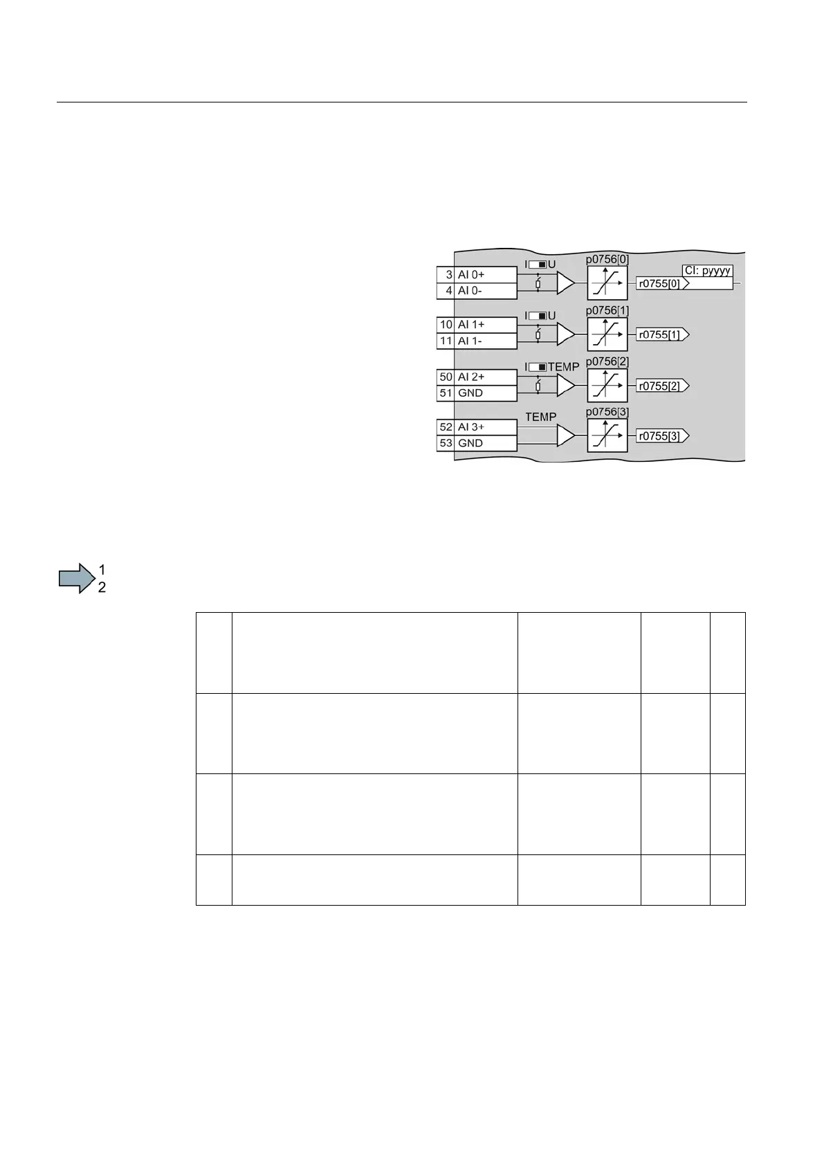
Analog inputs
Changing the function of an analog input
Define the analog input type using
parameter p0756 and the switch on
the inverter (e.g. voltage input -
10 V … 10 V or current input
4 mA … 20 mA).
Specify the significance of the analog
input by interconnecting parameter
p0755 with a connector input CI of
your choice, e.g. as speed setpoint.
The adjacent figure shows the terminals
of the analog inputs.
Define the analog input type
Procedure
Proceed as follows to define the analog input type:
1. Set p0756 to the appropriate value.
Unipolar voltage input
Unipolar voltage input monitored:
Unipolar current input
Unipolar current input monitored
Bipolar voltage input (factory setting)
0 V … +10 V
+2 V … +10 V
0 mA … +20 mA
+4 mA … +20 mA
p0756[0] = 0
1
2
3
Unipolar voltage input
Unipolar voltage input monitored:
Unipolar current input
Unipolar current input monitored
Bipolar voltage input (factory setting)
0 V … +10 V
+2 V … +10 V
0 mA … +20 mA
+4 mA … +20 mA
p0756[1] = 0
1
2
3
Unipolar current input (factory setting)
Unipolar current input monitored
Temperature sensor LG-Ni1000
Temperature sensor Pt1000
No sensor connected
0 mA … +20 mA
+4 mA … +20 mA
p0756[2] = 2
3
6
7
8
Temperature sensor LG-Ni1000
Temperature sensor Pt1000
No sensor connected (factory setting)
p0756[3] = 6
7

 Loading...


