2
Only connect to a UL864/ULC-S527 approved, power-limited, and regulated power
unit, e.g., PSC-12 / PSC-12M (TB3).
Port x*: modem or RS485 interface. The same interface type must be used on each
COM-2 card. If only one interface card is being used on a COM-2 card, it must be
inserted into port 1 or port 3.
EOLR 120Ω, ¼W, P/N 104-820150
Wiring class X RS485 on HUB-4 FSI
1 2 3 4 5 6 7 8
9 10 11 12 13 14 15 16
17 18 19 20 21 22 23 24
ONE SLOT OF CC-5/CC-2
HUB-4
A
-
B
-
B
+
A
+
A
-
B
-
B
+
A
+
A
B B A
A
B B A
A1
B1
NC
EF1
A2
B2
NC
EF2
+
NC
-
Power A
Power B
Line 1
Line 2
SIEMENS
FN2013 / FN2014
Rx
Tx
Rx
Tx
NC NC NC NC NC NC NC
A1
B1
NC
EF1
A2
B2
NC
EF2
+
NC
-
Power A
Power B
Line 1
Line 2
SIEMENS
FN2013 / FN2014
Rx
Tx
Rx
Tx
NC NC NC NC NC NC NC
+
+
_
_
+
+
_
_
EOLR
Port 1
DC 42 V
[1]
[2]
Port 3 Port 4
[3] [3]
DC 42 V
[2]
Port 2
[3]
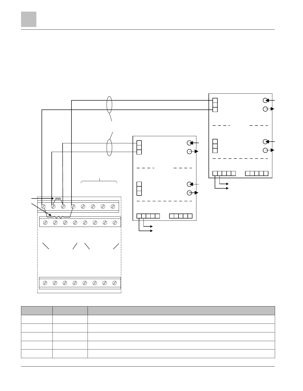
Fig. 6: Class X, RS485/HUB-4 FSI wiring (two FN2013/FN2014 required)
Pin Designation Description
Port 1/1 A + HUB-4, circuit 1A+, EOLR1, not monitored
1
Port 1/2 B + HUB-4, circuit 1B+, EOLR2, not monitored
1
Port 1/3 B - HUB-4, circuit 1B-, EOLR2, not monitored
1
Port 1/4 A - HUB-4, circuit 1A-, EOLR1, not monitored
1
EF1/A1 + Fiber network module, circuit 1A +/circuit 1B +, not monitored
Fiber network module FN2013/FN2014
Wiring
1
12 | 28 2023-01-23 A6V12093642_en--_b
 Loading...