Wiring class B HNET/XNET on NIC-C
1 2 3 4 5 6 7 8
NC
NC
NC
ONE SLOT OF CC-5/CC-2
NIC-C
A1
B1
NC
EF1
A2
B2
NC
EF2
+
NC
-
Power A
Power B
Line 1
Line 2
SIEMENS
FN2013 / FN2014
Rx
Tx
Rx
Tx
NC NC NC NC NC NC NC
9 10 11 12 13 14 15 16
17 18 19 20 21 22 23 24
DC 24 V
+
+
_
_
[1]
[2]
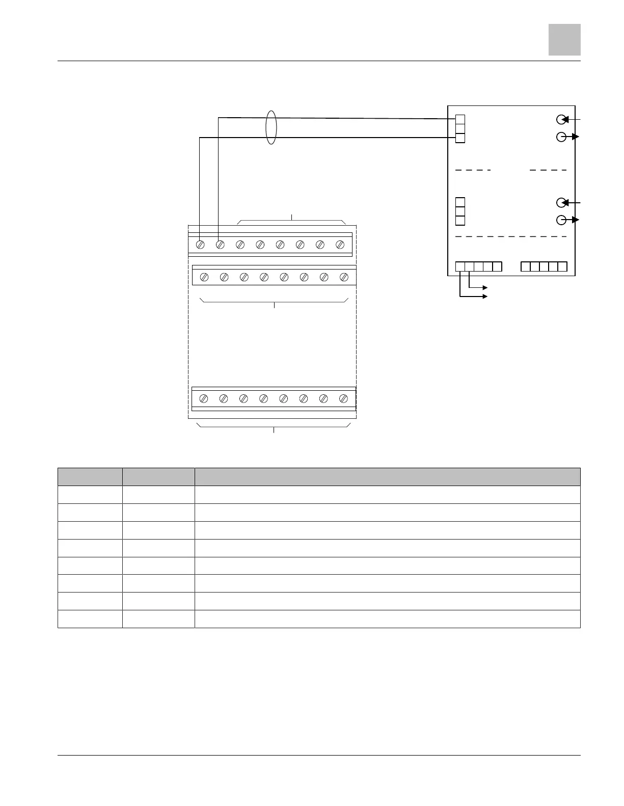
Fig. 3: Class B, HNET/XNET wiring on NIC-C
Pin Designation Description
NIC-C/1 - NIC-C,RS48 circuit 1 -, monitored by NIC-C
1
NIC-C/2 + NIC-C, RS48 circuit 1 +, monitored by NIC-C
1
NIC-C/3-24 NC NIC-C, do not use
EF1/A1 + Fiber network module, RS485 circuit 1 +
EF1/B1 - Fiber network module, RS485 circuit 1 -
Power A/+ + Fiber network module, + DC24V
2
Power A/- - Fiber network module, GND
2
Power B NC Fiber network module, do not use
1
RS485 ratings:
- 8 V P-P, 150 mA max.,
- 2000 ft/610 m max
- 16 AWG max., 18 AWG min.,
- Positive or negative ground fault supervision at < 10 kΩ
2
Only connect to a UL864/ULC-S527 approved, power-limited, and regulated power
unit, e.g., PSC-12 / PSC-12M (TB3).
No EOL resistor required on NIC-C or fiber network module.
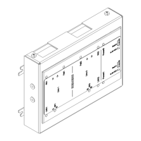
Fiber network module FN2013/FN2014
Wiring
1
A6V12093642_en--_b 2023-01-23 9 | 28
 Loading...