1.3 Views
F
a
i
l
1
R
X
1
L
N
K
1
E
F
1
L
N
K
2
P
o
w
e
r
A
F
a
i
l
2
R
X
2
P
o
w
e
r
B
L
i
n
e
1
L
i
n
e
2
E
F
2
1
4
6
5
5
5
8 37
2 3
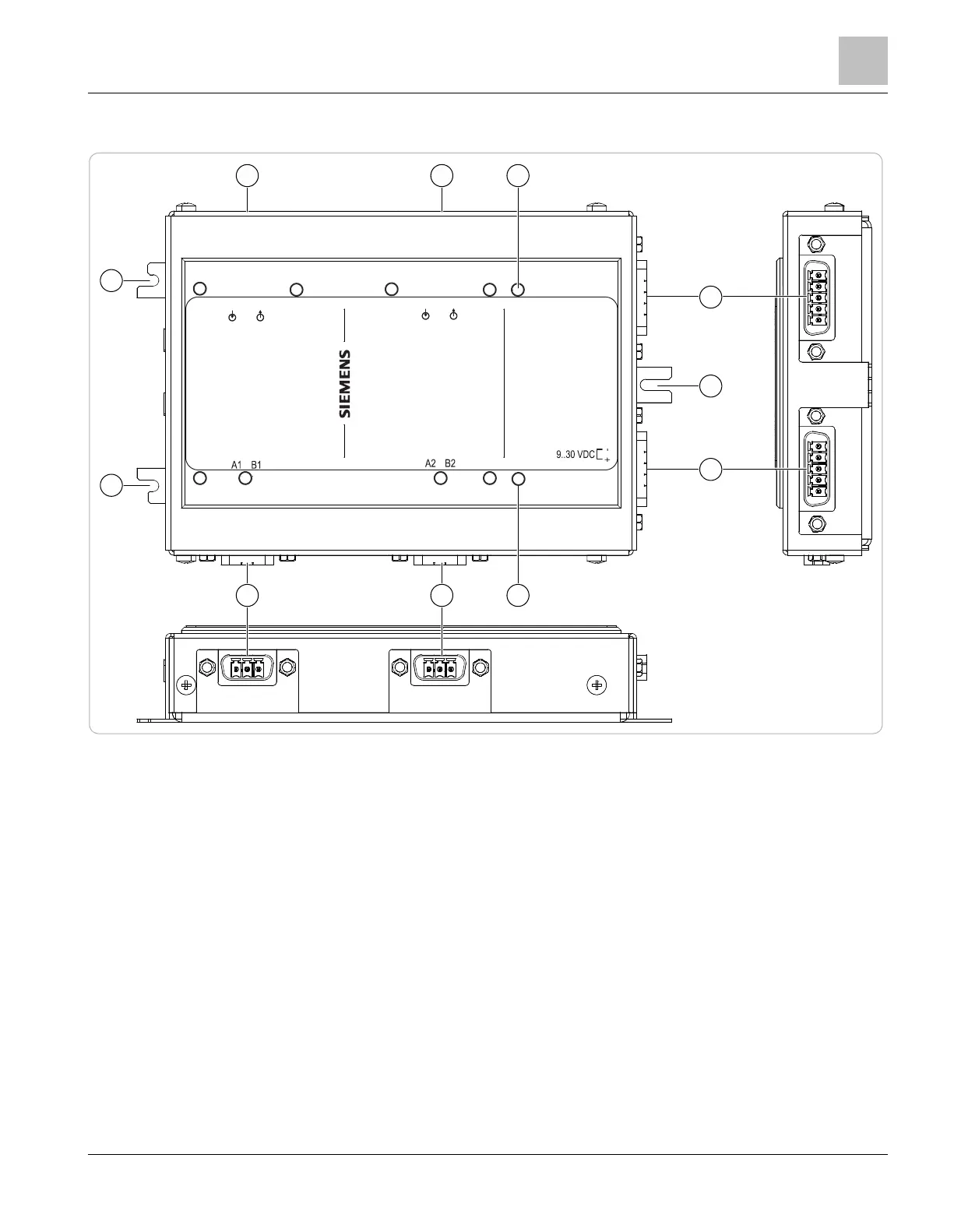
Fig. 2: Views of the fiber network module from above and the side
1 Fiber-optic SC connection for circuit 1
2 Fiber-optic SC connection for circuit 2
3 10 LED indicators for data transmission, errors and power supply for both
channels
4 Power B socket, do not use
5 Fastening tab for housing mounting
6 Power A socket, power supply
7 A2/B2 socket for HNET, XNET, HUB-4, SNC
8 A1/B1 socket for HNET, XNET, HUB-4, SNC
Fiber network module FN2013/FN2014
Views
1
A6V12093642_en--_b 2023-01-23 7 | 28
 Loading...