Pin Designation Description
EF1/B1 - Fiber network module, circuit 1A -/circuit 1B -, not monitored
Power A/+ + Fiber network module, + DC24V
2
Power A/- - Fiber network module, GND
2
Power B NC Fiber network module, do not use
1
RS485 ratings:
- 8 V P-P, 150 mA max.,
- 20 ft/6 m max. in conduit, not monitored
- 16 AWG max., 18 AWG min.
2
Only connect to a UL864/ULC-S527 approved, power-limited, and regulated power
unit, e.g., PSC-12 / PSC-12M (TB3).
Port x*: modem or RS485 interface. The same interface type must be used on each
COM-2 card. If only one interface card is being used on a COM-2 card, it must be
inserted into port 1 or port 3.
EOLR 120Ω, ¼W, P/N 104-820150
Wiring class B to an SNC
SNC
A1
B1
NC
EF1
A2
B2
NC
EF2
+
NC
-
Power A
Power B
Line 1
Line 2
SIEMENS
FN2013 / FN2014
Rx
Tx
Rx
Tx
NC NC NC NC NC NC NC
+
_
++
__
AB
EOLR
EOLR
DC 42 V
[1]
[2]
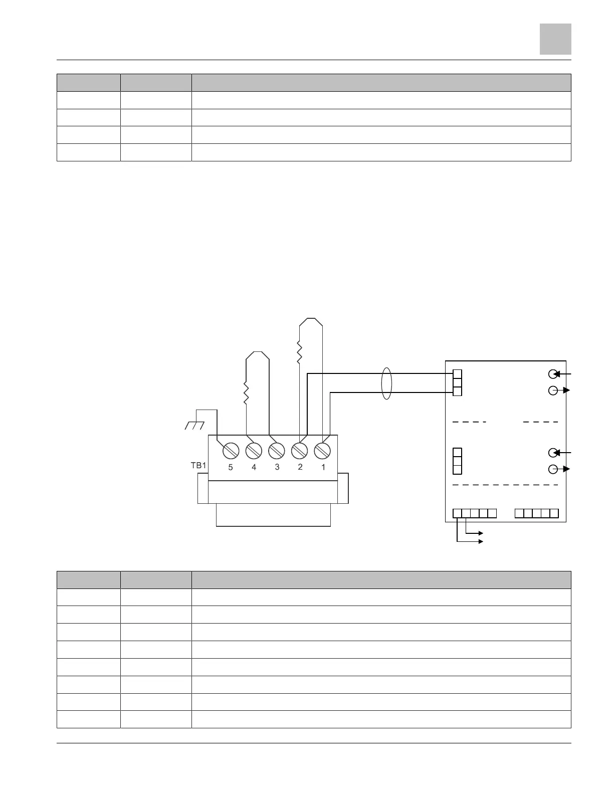
Fig. 7: Class B wiring to an SNC (Desigo CC/Cerberus DMS/NCC)
Pin Designation Description
SNC/1 - SNC, circuit A -, EOLR, not monitored
1
SNC/2 + SNC, circuit A +, EOLR, not monitored
1
SNC/3 - SNC, circuit A -, EOLR
SNC/4 + SNC, circuit A +, EOLR
SNC/5 Ground
EF1/A1 + Fiber network module, circuit A +, not monitored
EF1/B1 - Fiber network module, circuit A -, not monitored
Power A/+ + Fiber network module, + DC24V
2
Fiber network module FN2013/FN2014
Wiring
1
A6V12093642_en--_b 2023-01-23 13 | 28
 Loading...