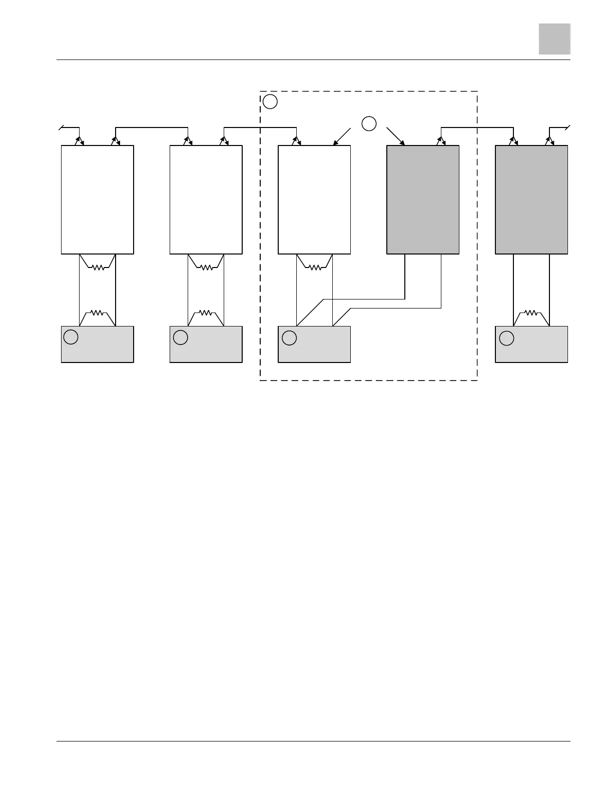
Adding a new panel to an existing cascade (daisy chain)
Tx Rx Tx Rx Tx Rx Tx Rx Tx Rx Tx Rx Tx Rx Tx Rx Tx Rx Tx Rx
D23XX D23XX D23XX FN2013/14 FN2013/14
1
2
3
4
FACP FACP
FACP
FACP
3
3
A
B
C
RS485
EF1
RS485
C
RS485
C
RS485
EF1
RS485
L1
L2
A
B
A
B
L1
L2
EOLR EOLR EOLR
EOLR EOLR EOLR
Fig. 14: Adding a new panel in cascade
L1 Fiber-optic SC connection circuit 1 on FN2013/FN2014
L2 Fiber-optic SC connection circuit 2 on FN2013/FN2014
EF1 Connection A1/B1, RS485 on FN2013/FN2014
A Fiber-optic SC connection circuit A on D23xx
B Fiber-optic SC connection circuit B on D23xx
C RS485 connection on D23xx
1 Shared housing
2 Fiber-optic cables are not permitted inside the housing
3 Existing fire control panel
4 New fire control panel
EOLR Terminating resistor 120 Ω
A terminating resistor is not necessary at the EF1 connection on FN2013/FN2014.
Fiber network module FN2013/FN2014
Appendix
1
A6V12093642_en--_b 2023-01-23 23 | 28
 Loading...