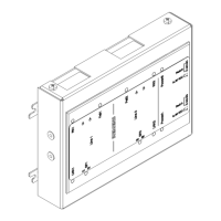
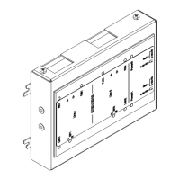
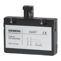
1
RS485 ratings:
- 8 V P-P, 150 mA max.,
- 20 ft/6 m max. in conduit, not monitored
- 16 AWG max., 18 AWG min.
2
Only connect to a UL864/ULC-S527 approved, power-limited, and regulated power
unit, e.g., PSC-12 / PSC-12M (TB3).
EOLR 120Ω, 1/2W, P/N 104-820350
Fiber optic cable wiring
● The accessible laser radiation is harmless. It corresponds to laser class1 in
accordance with IEC60825/ANSIZ136.
● The fiber-optic cable is wired cross-wise:
– The optical transmitter (TX) of one device must always be connected with
the optical receiver (RX) of the other device.
– Circuit1 must always be connected with circuit2.
● The bending radius of the fiber-optic cable must not be less than that specified by
the manufacturer (e.g. 10xouter diameter).
1.4.2 Power supply sockets (4, 6)
The 5-pole connectors for the power supply are supplied with the fiber network module.
Pin Designation Description
1 DC24V+ Supply input + of DC24V AUX from periphery board or CC-2/CC-5
2 DC24V- Supply input - of DC24V AUX from periphery board or CC-2/CC-5
3 - Do not use
4 - Do not use
5 - Do not use
Admissible cable cross-section: 16…18AWG
● When the module is installed in fire control panels or fire voice control panels
alone, the power supply does not have to be supervised or routed redundantly.
● The supply line for a remote network module must be shielded.
Fiber network module FN2013/FN2014
Wiring
1
A6V12093642_en--_b 2023-01-23 15 | 28

 Loading...


