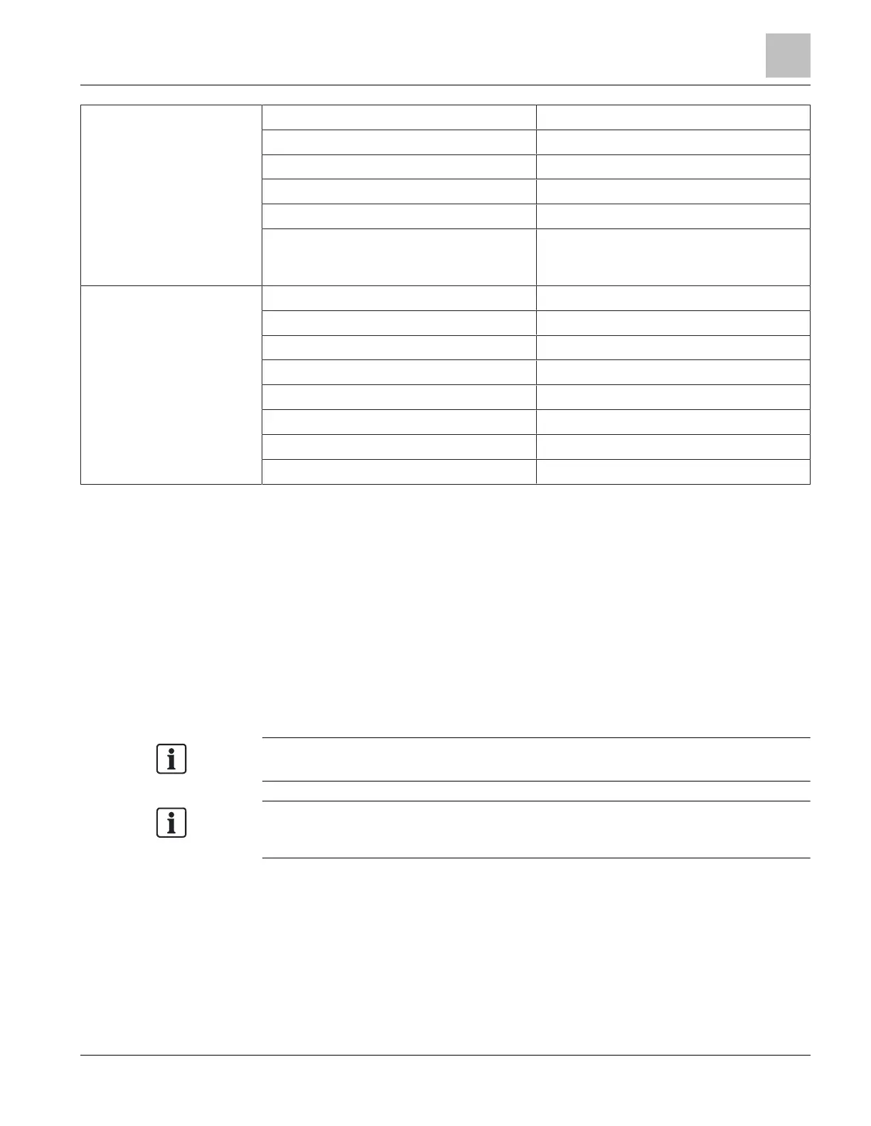
FN2013-U1 Single mode
Range:
● Fiber type 9/125µm 131000ft/40000m
Optical budget:
● Fiber type 9/125µm 29dBm
● Minimum optical attenuation
(corresponds to a minimum fiber
length of 13000ft/3962m)
3dBm
RS485 connection
[EF1], [EF2]
(HNET, XNET, HUB-4,
SNC)
Length of line: HNET, XNET (NIC-C) 2,000ft/610m at 19.2kbit/s
Length of line: HUB-4, SNC 20ft/6m in conduit
Impedance 60Ω
Transmission mode Half-duplex
Voltage/current 8V P-P, 150mA
Supervision
1
No ground fault supervision
Terminating resistor No EOL required
Cable type Shielded and unshielded cables
1
For connections via HNET/XNET, ground fault supervision is via the NIC-C.
1.7 Appendix
1.7.1 Applications for FN2013 and FN2014 modules
The diagrams below show typical applications for the FN2013 and FN2014. Class B
networks are shown; for class X, two of every device are required and must be
connected in a parallel (redundant) network. Fiber-optic cables L1 and L2 are
interchangeable. L1 does not always have to be connected to L2. All fiber-optic cables
in the diagrams below are connected with two fibers between the FN2013/14 modules.
Mixing of single-mode and multi-mode fibers is not permitted.
Connect the EF1 port on FN2013 or FN2014. An external terminating resistor is not
necessary because there is an internal 120 Ω terminating resistor installed at the EF1
port.
Fiber network module FN2013/FN2014
Appendix
1
A6V12093642_en--_b 2023-01-23 19 | 28
 Loading...