FACP Fire control panel
MMS Management station
EOLR Terminating resistor 120 Ω
All modules connected via fiber-optic cables must be the same model (FN2013 or
FN2014) and use the same type of fiber (multi-mode or single-mode). Mixing of module
types and types of fiber is permitted on the RS485 network.
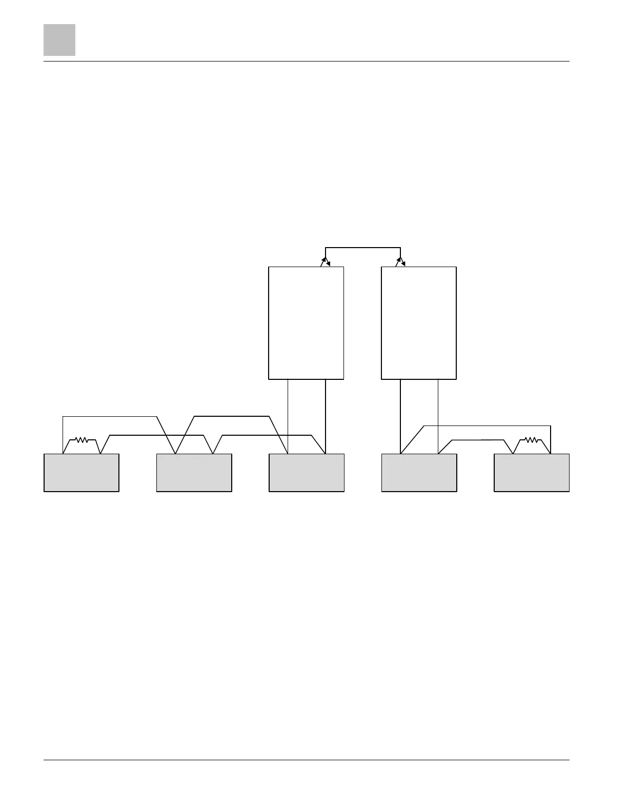
FN2013 or FN2014 modules in the center of the RS485 daisy chain must be connected
to the EF2 port. If an FN2013 or FN2014 is located at one end of the chain, connect it
to the EF1 port which has an internal 120-ohm terminating resistor; an external
terminating resistor is not necessary.
Fiber-optic bridge
FACP FACP FACP FACP FACP
FN2013/14
Tx Rx Tx Rx
FN2013/14
Tx Rx Tx Rx
EF1
RS485
L1
L2
EF1
RS485
L1
L2
EOLR EOLR
Fig. 13: Fiber-optic bridge
L1 Fiber-optic SC connection for circuit 1
L2 Fiber-optic SC connection for circuit 2
EF1 Connection A1/B1, RS485
FACP Fire control panel
EOLR Terminating resistor 120 Ω
1.7.2 Integrating FN2013/FN2014 into existing D23xx networks
The diagrams below show typical applications for D2300CPS/D2325CPS modules and
how FN2013 or FN2014 modules can be added to existing fiber-optic networks with
D23XXCPS modules. Class B networks are shown; for class X, two of every device are
required and must be connected in a parallel (redundant) network. Fiber-optic cables
L1 and L2 on the FN2013 or FN2014 are interchangeable. L1 does not always have to
be connected to L2. All fiber-optic cables in the diagrams below are connected with two
fibers between the D23XX or FN2013/14 modules.
Fiber network module FN2013/FN2014
Appendix
1
22 | 28 2023-01-23 A6V12093642_en--_b
 Loading...