140/245
Building Technologies Division Basic Documentation LME7... CC1P7105en
Infrastructure & Cities Sector 18 PME73.831… 29.11.2011
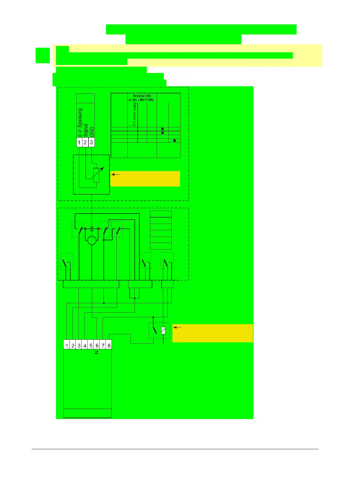
18.4 Connection diagram for LME73.000... with
actuator SQM4... (example 2)
Note:
The connection diagram shown is merely an example which must be verified in the individual case
depending on the application!
PME73.831... 1-stage modulating
With/without pilot ignition
With/without valve proving
X3X2X1
123
V
IV
III
5
M
III
I
21
3
41
2345
6
I
VI
V
IV
III
II
7105d64e/1210
X2-09
SA-Z
SA-KL
SA-NL
SA-R
PE
Input SA-ZL cams
Output SA-ZL cams
X66
ASZ12.33
ab
c
Type
SQNx1...
SQMx1...
SQNx0...
SQMx0...
2
(Signal)
3
(GND)
a
b
c
a
b
c
a
b
c
a
b
c
Terminal potentiometer
(1 kOhm conductive 90°)
ASZxx30
Direction of
rotation
Clockwise
Counter-
clockwise
---
---
---
---
N
External relay
for pilot valve
Ignition load
Low-fire
CLOSE
High-fire
Only required for modulation via
analog signal (0...10 V, 4...20 mA,
0... 135 Ohm) (parameter 560 = 2)!
Only required if switching load
of cam switch in the actuator
Is lower than the current consumption
of the pilot valve!
Fig. 73: Connection diagram for LME73.000... with actuator SQM4... (example 1)
 Loading...