93/245
Building Technologies Division Basic Documentation LME7... CC1P7105en
Infrastructure & Cities Sector 15 PME73.810... 29.11.2011
15 PME73.810...
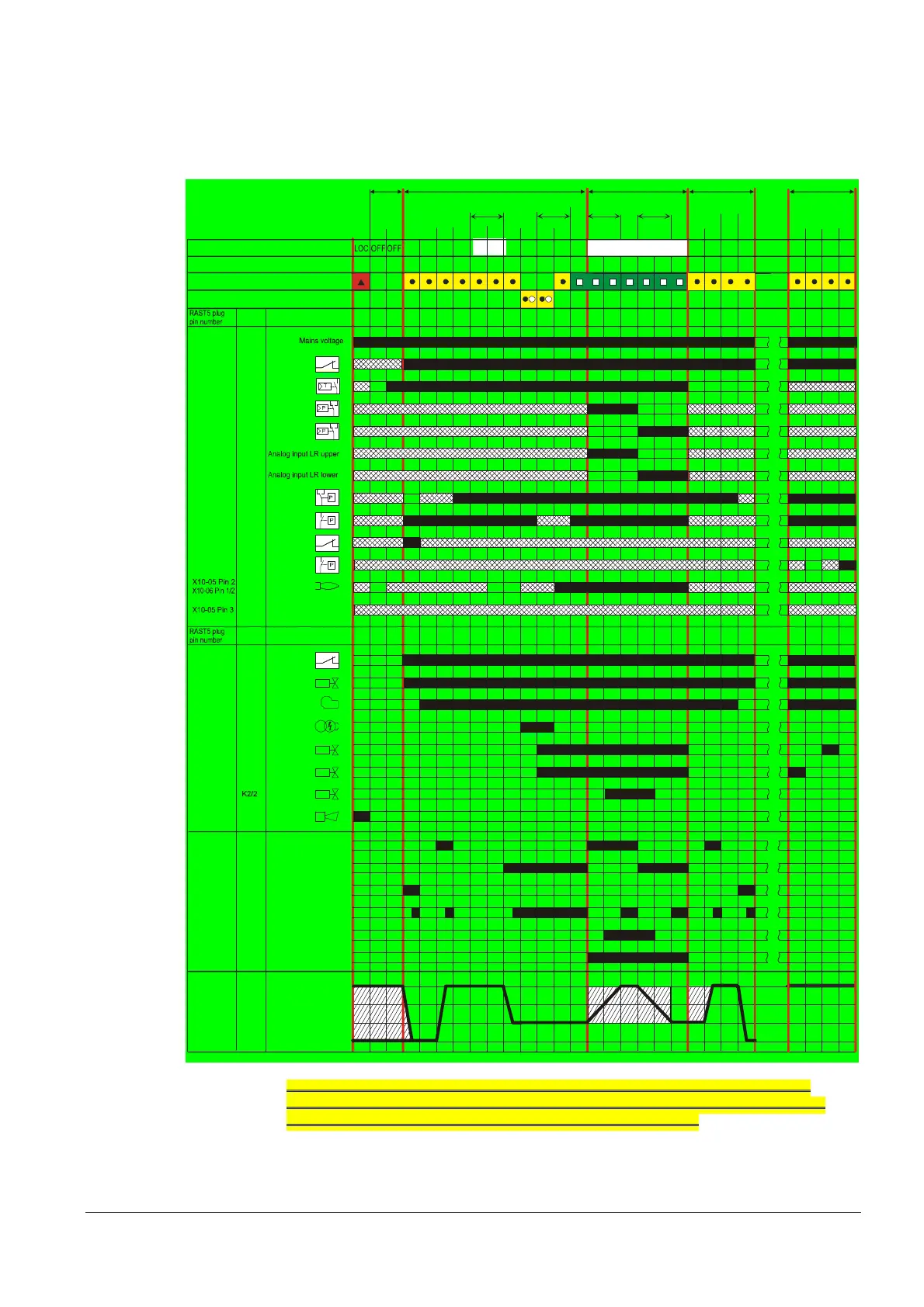
15.1 Program sequence PME73.810...
For connection diagram fuel train (G) without valve proving
For connection diagram fuel train (G) with valve proving
For connection diagram actuator application example 1
710 5d 74e/ 1111
M
Z
V1
V2a
AL
K1X2-02 Pin 3
Actuator position
High-fire
Cam V2
Ignition load / low-fire
CLOSE
R
LR-AUF
LR-ZU
LP
Pmin
P LT
ION / QRA
Not active
X3-04 Pin 5
Relay
contact
Function / inputs
Display and operation unit parameter number
LED permanent
LED flashing
tw t11 t10 t12 t3 t3n t4 t8 td4 td1 td3 td2
Standby Startup Operation Shutdown Valve proving
setzung If parameter
P241 =1 (ON)
Can be
parameterized
t1
TSA
259 225 260 226 257 234
Relay
contact
Function / outputs
SK
X3-04 Pin 1
X5-03 Pin 1
X5-03 Pin 3
X65 Pin 1
X5-03 Pin 2
X65 Pin 1
X3-02 Pin 1
X5-01 Pin 2
X2-02 Pin 4
X9-04 Pin 2
K1X6-03 Pin 3
K4X2-01 Pin 3
K5X4-02 Pin 3
K7X7-04 Pin 4
X7-01 Pin 3
K2/1X2-03 Pin 3
Phase number
21 22 24 22 30 30 36 38 40 42 44 72 74 10 80 81 82 83
oP: xx (Istleistung in %)
74
224
t11
POC
POC
240 240 240 240 240 240 242 243 244 245
t11 t12
SV
V2
K9X7-02 Pin 3
SA-KL
K12X2-09 Pin 2
SA-NL
K11X2-09 Pin 3
SA-Z
X2-09 Pin 1
SA-R
X2-09 Pin 4
Input from cam V2
X2-09 Pin 8
Output from cam V2
X2-09 Pin 7 K2/2
*) *) *) *)*)
*1
*2
Figure 38: Program sequence PME73.810... for connection diagram fuel train (G)
*) During the actuator running phases, the actuator feedback signal must be OFF first, then ON.
*1 Valve proving when P241 = 1 after mains ON, lockout or P234 (postpurge time t8) = 0 seconds
*2 Valve proving when P241 = 1 and P234 (postpurge time t8) >0 seconds
 Loading...