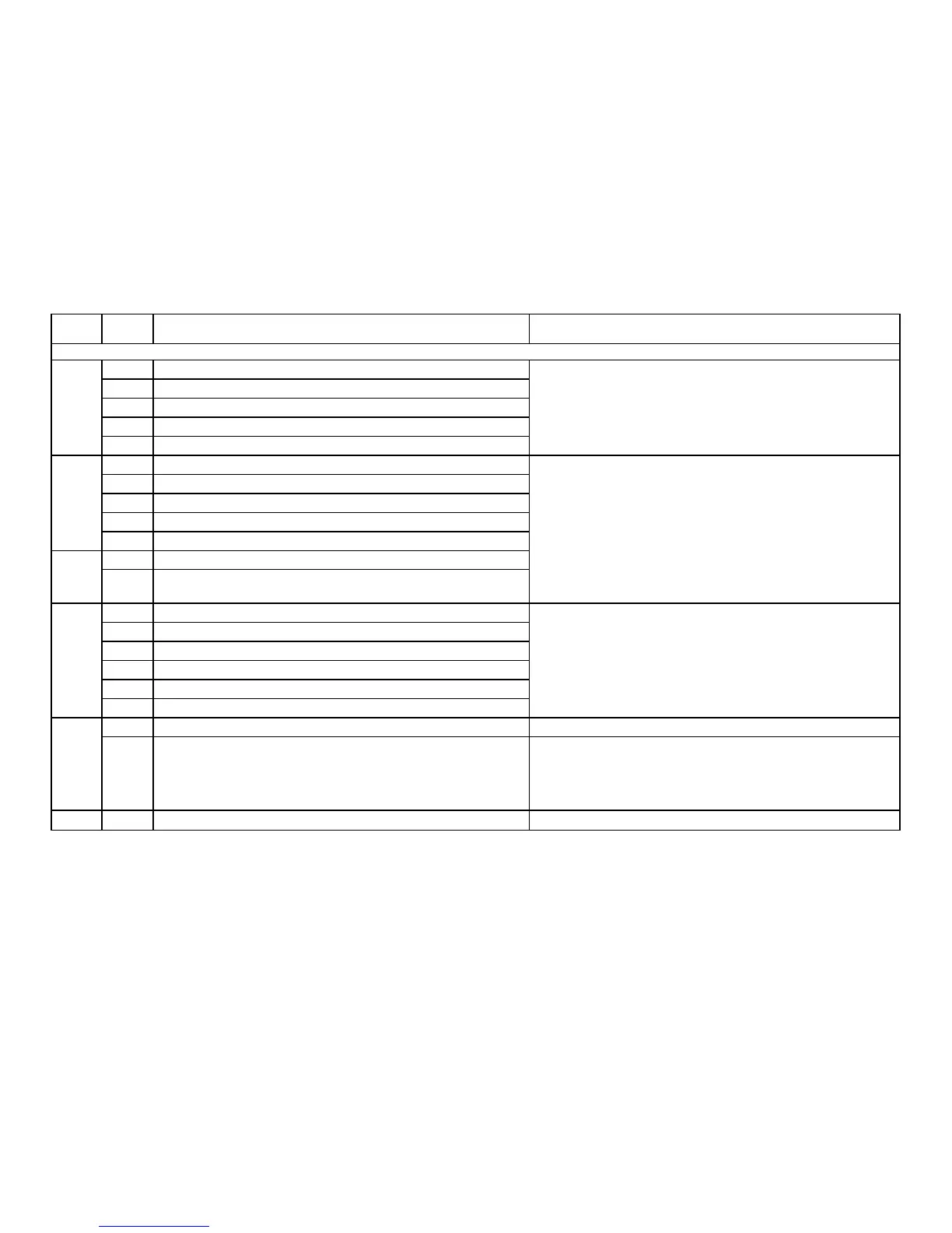
Meaning for the LMV3 System Corrective Action
Note: Diagnostic codes are additive. If a diagnostic code appears that is not on this list, it is a combination of multiple diagnostic codes.
Any # Error relay supervision
3 External power supply NO contact (ignition transformer - X4-02.3)
4 External power supply NO contact (fuel valve 1 - X8-02.1)
5 External power supply NO contact (fuel valve 2 - X7-01.3)
6 External power supply NO contact (pilot valve - X7-02.3)
Any # Error relay supervision
3 Relay contacts have welded (ignition transformer)
4 Relay contacts have welded (fuel valve 1)
5 Relay contacts have welded (fuel valve 2)
6 Relay contacts have welded (pilot valve)
Any # Error relay supervision
0
Safety relay contacts have welded or external power supply fed to safety
relay
Any # Error relay supervision
2 Relay does not pull in (safety valve - X6-03.3)
3 Relay does not pull in (ignition transformer - X4-02.3)
4 Relay does not pull in (fuel valve 1 - X8-02.1)
5 Relay does not pull in (fuel valve 2 - X7-01.3)
6 Relay does not pull in (pilot valve - X7-02.3)
Any # Internal error relay control If the fault occurs continuously, replace the LMV3.
3 Internal error relay control
On software version V03.10, if this error occurs during standardization of
the VSD, temporarily deactivate the alarm in the case of start prevention
(set parameter 210 = 0), reset the fault, and re-standardize. Otherwise, if
the fault occurs continuously, replace the LMV3.
100 Any # Internal error relay control If the fault occurs continuously, replace the LMV3.
95
96
97
99
98 If the fault occurs continuously, replace the LMV3.
Fix the wiring error / defective component causing the voltage feedback
and reset the fault.
Remove the wire from fan output terminal X3-05.1 and perform the
following two tests:
1. With power connected to the LMV3 and the LMV3 in standby, ensure
there is no voltage on fan output X3-05.1.
2. With no power connected to the LMV3, ensure there is no continuity
between fan output X3-05.1 and neutral.
If either test fails, replace the LMV3. If both tests are passed, reset the
fault.
Section 6 Page 16 SCC Inc.

 Loading...


