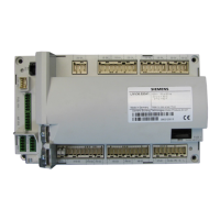
LMV Series
Technical Instructions
LV3-1000
Gas Oil Gas Oil U/S/O Default Range Description
LEGEND - Password Access: U = User, S = Service, O = OEM, U/S = View - User, Write - Service, S/O = View - Service, Write - OEM
Shaded Parameters = Frequently Used. ** Parameters = Must Set. Fuel 1 parameters for LMV36 only.
Parameter Name
VSD Speed Shift S/O 0 0-4
This setting enables 4-20 mA input X64 as the input for shifting the VSD speed off of the base curve. If
activated, terminal X64 will no longer accept a 4-20 mA input for the load. There are two additional options
to consider when activating VSD shift. The first is to enable the controller sending the 4-20 mA signal to
test the analog input during phases 24-30 (prepurge). The second is to enable ignition speed shift so that
the VSD speed at ignition position can be shifted to provide a more rich light off when the boiler is cold.
0 = deactivated (X64 remains as a 4-20 mA load input)
1 = activated
2 = activated (with analog input test)
3 = activated (with ignition speed shift)
4 = activated (with analog input test and ignition speed shift)
VSD Activation 0 0-1
This setting activates or deactivates a VSD:
0 = VSD deactivated
Modulation Ramp 32 sec 32-80 sec
This setting controls the speed at which the actuators will ramp during phases 60-62 (fuel valves open). The
time chosen is how long it would actually take for the actuators to drive from 0-90°. During all other
phases, the actuator ramp speed is fixed depending on the model of the SQM33 actuator being used
(SQM33.5 = 5 sec, SQM33.7 = 17 sec). If using a VSD, this time should be set at least 20% longer than the
longest VSD ramp time (parameters 522 and 523).
Load Low Fire Not set 20-100% Sets the low fire load. During normal operation, the burner will not modulate below this point.
Load High Fire Not set 20-100% Sets the high fire load. During normal operation, the burner will not modulate above this point.
VSD Shift Low -4% -15-0%
Sets the absolute lower limit for VSD speed shift. This percentage is based on the standardized speed
(parameter 642).
VSD Shift High 4% 0-25%
Sets the absolute upper limit for VSD speed shift. This percentage is based on the standardized speed
Shift Attenuation 88% 0-100%
The attenuation factor for VSD speed shift. This setting gives the ability to have less VSD shift at low fire for
a given analog input signal. 100% attenuation means that there will be no shift at low fire and maximum
shift at high fire with a linear interpolation between. A setting of 0% results in no attenuation, so the full
measure of VSD shift will be used at all firing rates.
Shift Delay 25 sec 0-255 sec
This setting is a delay timer for VSD speed shift. After the LMV3 reaches normal operation (phase 60), this
delay timer starts. After this time expires, the 4-20 mA input on X64 will be used to shift the VSD speed. A
setting of 0 seconds deactivates this feature.
Shift Limit Time 0 sec 0-3600 sec
If the LMV3 is at the upper or lower VSD shift limit (parameters 547/567 or 548/568) for this amount of
time, a warning message will be displayed or a shutdown will occur, depending on the setting of parameter
552/572. A setting of 0 seconds deactivates this feature.
Shift Limit Response 0 0-2
Determines the action of the LMV3 if the VSD shift limits are reached:
0 = warning only
1 = warning and VSD shift deactivation
S/O
551
567
568
569
570
571
546 566
542
552 572
530
544
545 565
S
547
548
549
550
SCC Inc. Page 12 Section 3
 Loading...


