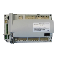
LMV Series
Technical Instructions
LV3-1000
Gas Train:
2, 8, 15, 20
(Pilot Gp1)
Lockout Phase
Safety Phase
Home Run Position
Burner Standby
Comb. Fan, SV = ON
Drive to Prepurge Pos.
Prepurge
VSD Drive to Ignition Pos.
Drive to Ignition Pos.
Preignition (Spark) = ON
Pilot Valve = ON
Ignition (Spark) = OFF
(Pilot Stabilization)
Safety Time 2
(Main Stabilization)
Operation 1
(Normal Operation)
Operation 2
(Driving to Low Fire)
Drive to Ignition Pos.
Interval 2
Ignition (Spark) + Pilot Valve
= ON
Main Valve = OFF
Pilot Waiting Time
Pilot Waiting Time - Startup
Afterburn Time
Drive to Postpurge Pos.
Mandatory Postpurge
Optional Postpurge
Evacuate
Atmospheric Test
Fill
Pressure Test
Gas Shortage
Phase 00 02 10 12 22 24 30 35 36 38 40 42 44 50 52 60 62 64 65 66 67 68 69 70 72 74 78 80 81 82 83 90
Terminal Description Notes
X3-04.1
Safety Loop (Limits)
X3-02.1
Blower Air Switch (APS) Note 1
X5-01.2
Low Gas Pressure Switch Note 2
High Gas Pressure Switch Note 2, 3
POC Note 3
X9-04.2
Valve Proving Pressure Switch
X3-05.3
Continuous Fan
X4-02.3
Ignition
X6-03.3
Gas Valve SV (Usually Outdoor)
X7-02.3
Gas Valve PV (Pilot Valve)
X8-02.1
Gas Valve V1 (Main, Upstream)
X7-01.3
Gas Valve V2 (Main, Downstream)
Must be energized by end of phase
Must be de-energized by end of phase
Energized or de-energized
START-UP
INPUTS
Start-up valve proving, if used.
GAS VALVE
PROVING
Parameter 208 (Program Stop)
OPER-
ATION
SHUTDOWN
Shutdown valve proving, if used.
OUTPUTS
X5-02.2
SAFETY
TIME 1
REVERT TO PILOT
SCC Inc. Page 21 Section 3
 Loading...


