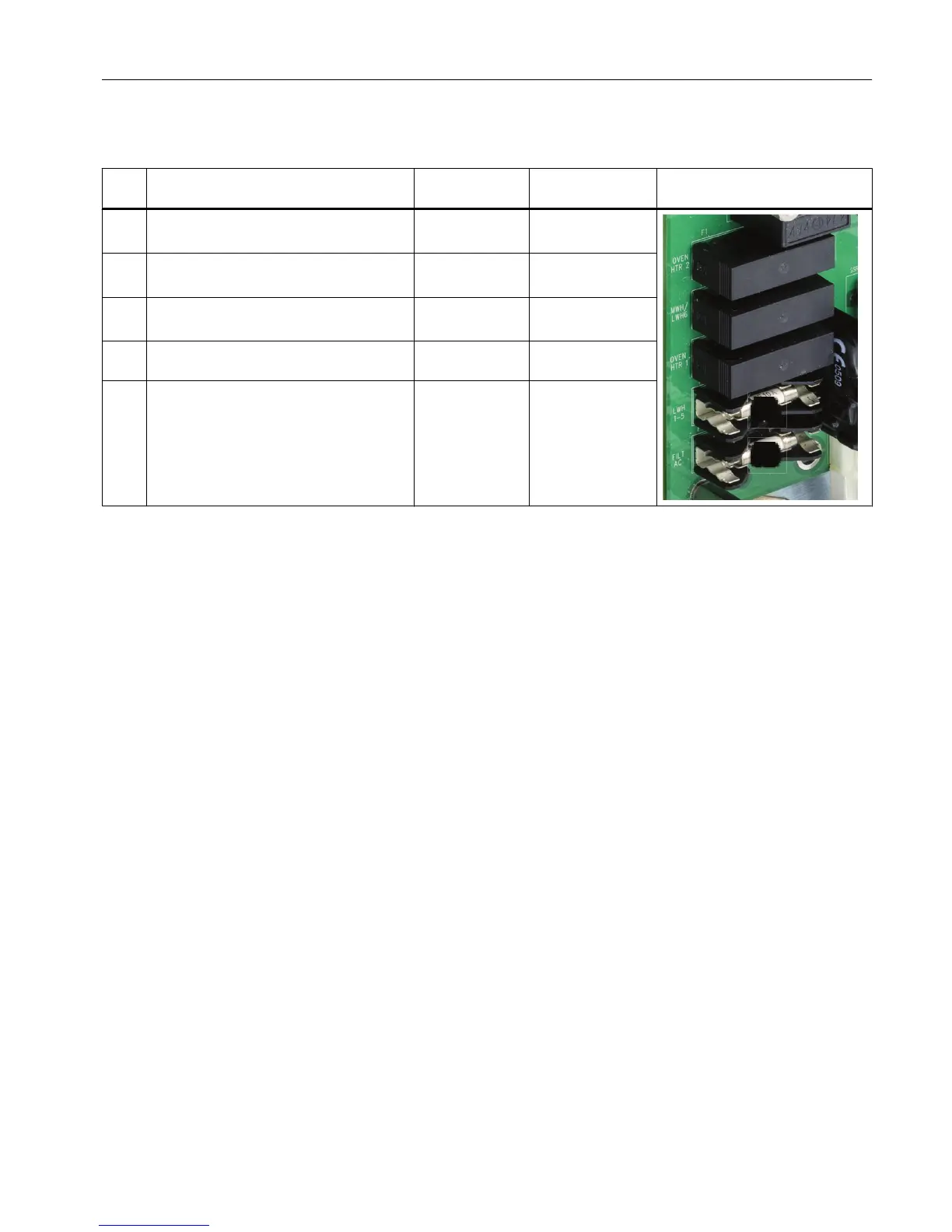
F5 Medium or low wattage heater channel 6
- MWH/LWH6
6.3 A
(1901695-001)
6.3 A
(1901695-001)
F2 AC power circuit 2 - Oven heater 1 16 A
(1901693-001)
10
A(1901694-001)
F4 Low wattage heaters 1-5 - LWH1 - LWH5 10
A(1901694-001)
10
A(1901694-001)
F3 Power supply (24 VDC) - FILT AC 3.15 A
(1302004-033)
3.15
A(1302004-033)
2.2.3.2 Oven Temperature Control
Oven Temperature Monitoring and Control: The PECM_CTL board has two temperature
monitor and control channels for use with the high-wattage heaters (HWH) and medium-
wattage heaters (MWH). Each channel includes;
● RTD input
● Mounting location and connector for set point resistor module
● Comparator circuit
● PWM control signal output
● Control input (can accept an external control signal from another module if desired)
● Control output for High or Medium Wattage Heater Solid State Relay module
● AC power output for High or Medium Wattage Heater Solid State Relay
Each circuit consists of two series-connected solid-state relays. One of these relays controls
the 1400-Watt or 650-Watt AC heater to maintain the set point temperature by monitoring the
air bath RTD and heater pressure switch. The second relay is used for safety purposes. It
performs an emergency analyzer heater shutdown if an over-temperature condition is
detected. Both relay circuits are completely independent of each other. However; in order for
the power circuit to be energized, both relays must be enabled. Temperature controls are
monitored by the Detector Personality Module and routed to the PECM via a dedicated cable
and connector, or by the temperature-control circuits on the PECM-CTL board itself. No other
functions are connected to the temperature control circuit. When over temperature is detected
the PECM over temperature circuit inhibits the SSR from powering the heater and stays off
until power is reset. Alarm conditions are reported to the SYSCON over the I
2
C link.
Electronic Compartment Component Descriptions and Maintenance Procedures
2.2 Power Entry and Control Module
Maxum II Reference Manual
Manual, 7/2017, 2000596-001 21

 Loading...


