EasyManuals Logo

Siemens Maxum II Reference Manual

Siemens Maxum II
100 pages
To Next Page IconTo Next Page
To Previous Page IconTo Previous Page
Page #22 background imageLoading...
Page #22 background image
Compare
Airflow
Loss
Shutdown
PECM
Air Bath Oven
High-Wattage
Heater
Analog
SSR Pair
Air Pressure
Switch
Digital
Temp Control,
Temp Limit,
Overtemp RTDs
Temp
Setpoint
Modules
PWM
I
2
C
Temperature
Control
Airflow Loss
Shutdown
Heater
AC
Line
SSRa SSRb
SYSCON
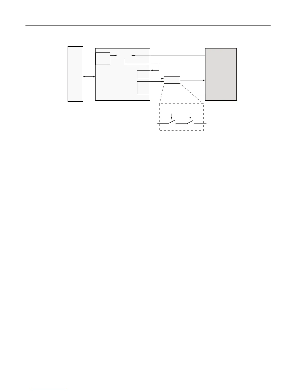
Figure 2-6 PECM Heater Control Functions
2.2.3.3 Communication and Power Distribution
The 24V power supply connects to one of two parallel power connectors, TB1 and TB2 on the
PECM-CTL board. Another module can be powered from the other connector.
Each of the 7 I
2
C connectors also provides 24VDC power to the connected module.
A separate connector powers a 24V fan.
Electronic Compartment Component Descriptions and Maintenance Procedures
2.2 Power Entry and Control Module
Maxum II Reference Manual
22 Manual, 7/2017, 2000596-001

Table of Contents

Other manuals for Siemens Maxum II

Questions and Answers:

Question and Answer IconNeed help?

Do you have a question about the Siemens Maxum II and is the answer not in the manual?

Siemens Maxum II Specifications

General IconGeneral
CategoryGas Chromatograph
Measurement PrincipleGas Chromatography
Communication ProtocolsModbus, Ethernet, Profibus
Operating Temperature-20°C to 55°C
Power Supply24 VDC or 100-240 VAC
Mountingrack mount
ApplicationsRefinery, chemical, petrochemical, natural gas
DetectorsThermal Conductivity Detector (TCD), Flame Ionization Detector (FID)
Sample InletsMultiple
DimensionsVaries by configuration (e.g., 19" rack mount)

Related product manuals