2.7 Solid State Relay Module
The Solid State Relay (SSR) Module is made up of two pairs of high wattage heater relays
that are used for controlling the oven air bath heaters. One pair controls ABH1 and the other
ABH2. Each pair of relays controls Temperature Limit and Oven Temperature shut down. If
the over temperature limit is exceeded, the power to the air bath heater is shutdown. Two
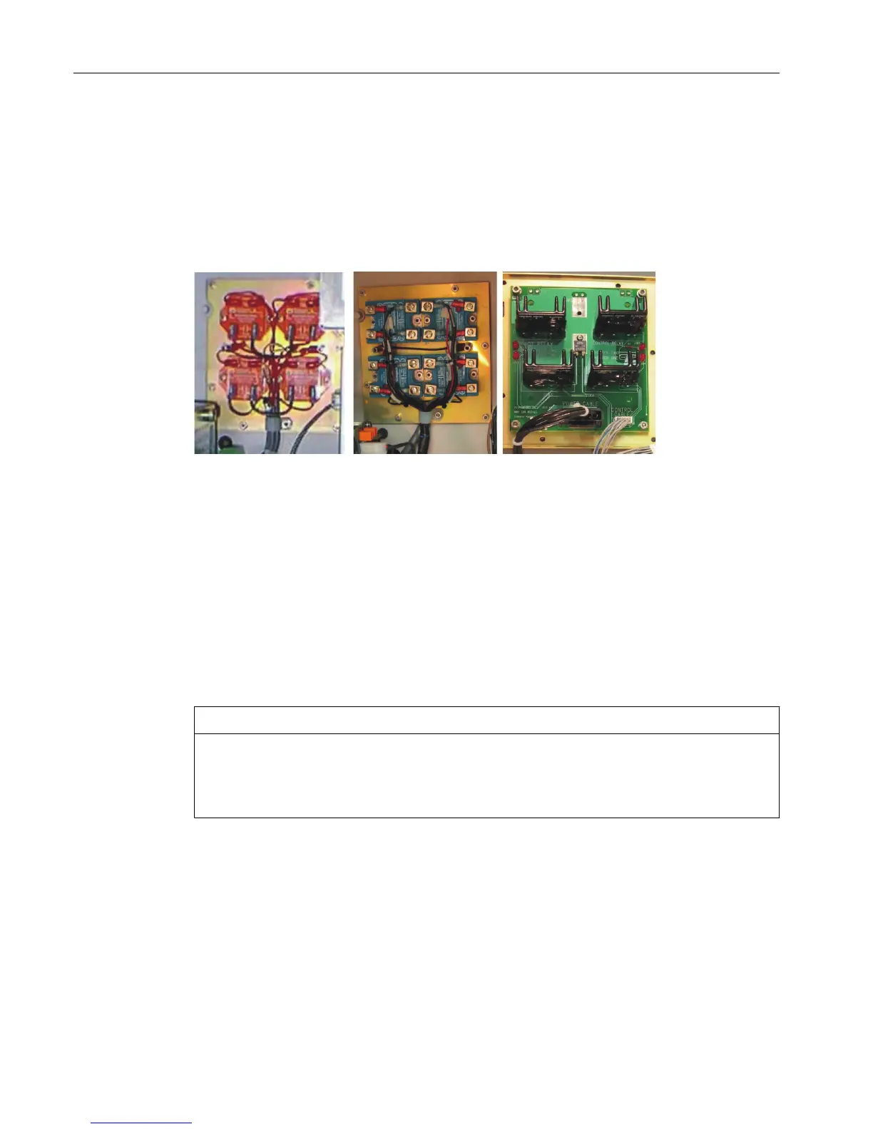
different configurations of SSR are available, the SSR and the Medium Wattage SSR. There
are also original and new versions of the standard SSR.
Figure 2-37 Solid State Relay Modules
The SSR module assembly is mounted to the left side of the EC back wall. A metal cover not
shown in the photograph above protects the relays for the standard version of the SSR. The
standard version of the SSR is equipped with heat dissipating fins that extend through the back
of the enclosure wall to dissipate generated heat to the outside atmosphere. The medium
wattage version dissipates heat to the interior of the electronics enclosure using heat sinks.
The standard SSR, also called high wattage, can provide switching for two heater elements
of up to 1400 watts each. The medium wattage version can control two heater elements of up
to 500 watts each. Relays for both the original and new standard SSR versions are available
as spare parts. For the medium wattage SSR, individual relays cannot be replaced.
NOTICE
The SSR module supports either 115 VAC or 230 VAC power. For 115 VAC power the in-line
fuses to the SSR should be rated at 16 A. For 230 VAC, the fuses must be rated at 10 A. DO
NOT use a 16 A rated fuse for 230 VAC primary AC power. This could result in overheating
and equipment damage.
High Wattage SSR
The relays on the newer SSR provide an indicator LED which shows the operational status of
the control signals. In addition the newer SSR is equipped with a plastic shield which covers
the connection screw terminals and helps prevent inadvertent contact. Note, however, that
the older SSR is entirely enclosed in a sheet metal housing so human contact is not possible
without disassembly of the module.
Electronic Compartment Component Descriptions and Maintenance Procedures
2.7 Solid State Relay Module
Maxum II Reference Manual
74 Manual, 7/2017, 2000596-001

 Loading...


