Additional Relay Outputs
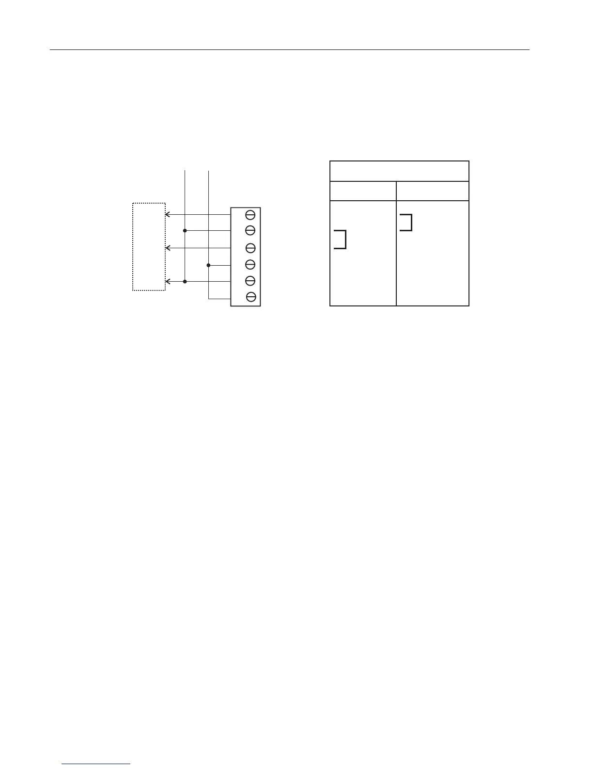
Relay circuits LWH5 and LWH6 when used for purposes other than on/off control of low
wattage heaters can supply four separate outputs. A simple jumper on pins 1 to 2 on output
connector TB7 or TB8 makes this possible. With the jumper in place, each connector will
provide two independent outputs; see the diagram below.
Figure 2-8 LW5 & LW6 Relay Circuit Jumper Connections
2.2.3.5 Oven Functions
Temperature Monitoring and Control
The PECM_CTL board has two temperature monitor and control channels for use with the high-
wattage heaters (HWH). Each channel includes;
● RTD input
● Mounting location and connector for
setpoint module
● Comparator circuit
● PWM control signal output
● Control input (can accept an external
control signal from another module if
desired)
● Control output for HWH SSR module
● AC power output for HWH SSR
The HWH control path is shown below.
Electronic Compartment Component Descriptions and Maintenance Procedures
2.2 Power Entry and Control Module
Maxum II Reference Manual
24 Manual, 7/2017, 2000596-001

 Loading...


