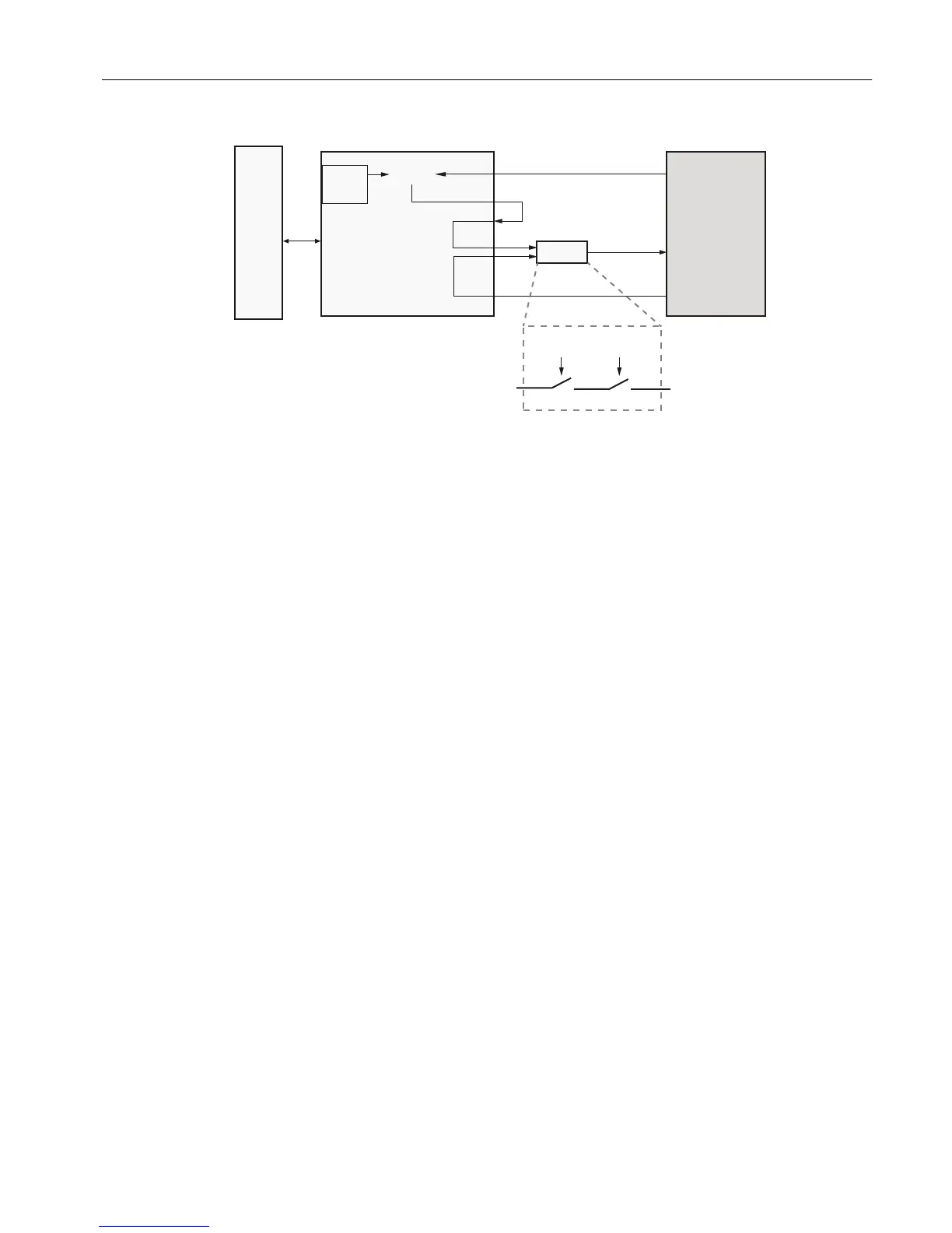
Figure 2-9 PECM Heater Control Functions
Each circuit consists of two series-connected solid-state relays. One of these relays controls
the 1400-Watt AC heater to maintain the set point temperature by monitoring the air bath RTD
and heater pressure switch. The second relay is used for safety purposes. It performs an
emergency analyzer heater shutdown if an over-temperature condition is detected. Both relay
circuits are completely independent of each other. However; in order for the power circuit to
be energized, both relays must be enabled. Temperature controls are monitored by the
Detector Personality Module and routed to the PECM via a dedicated cable and connector, or
by the temperature-control circuits on the PECM-CTL board itself. No other functions are
connected to the temperature control circuit. The connections are EMC filtered. When over
temperature is detected the PECM over temperature circuit inhibits the SSR from powering
the heater.
Alarm conditions are reported to the SYSCON over the I
2
C link.
Solenoid Control
Includes solenoid valve control which eliminates the need for individual SVCM controller
boards. When converting older design and eliminating original SVCM controller boards,
additional long cables are required.
Air-Supply Monitoring for Air-Bath Oven
The 1400-watt heater assembly is used in many air bath configurations (single isothermal;
dual isothermal; or Programmed Temperature Control). A single heater is used for the single
isothermal configuration and two heaters are used in the other configurations.
Additionally, a “medium power” Solid State Relay Module (temperature control relay module)
is available. These smaller relays are capable of controlling the 500 watt air bath heater
assembly. This can be used in single isothermal configurations where the controlled oven
temperature is 70°C or less. In addition, the “medium power” SSR Module can be used to
control the two 250 watt heaters used in the Maxum airless oven configurations.
See the
PECM3 I/O Connections
diagram in
PECM Overiew
for connector locations.
Electronic Compartment Component Descriptions and Maintenance Procedures
2.2 Power Entry and Control Module
Maxum II Reference Manual
Manual, 7/2017, 2000596-001 25

 Loading...


