2.4.4 Analog and Digital IO Board
Circuits on the ADIO board are wired as shown in the following table. The table is the view as
seen when looking at the connector while the board is installed.
Table 2-3 ADIO_I2C Wire Side View
Signal Pin Signal
AI4 -10V 2 1 AI4 +10V Analog Inputs: -20 to 20mA into 50Ω or -10 to 10V, R10=1MΩ,
mutually isolated 10V
Analog Outputs: 0-4 to 20mA. Common negative pole, galvani‐
cally separated from ground, freely connectable to ground; work‐
ing resistance 750Ω.
Digital Inputs: Optocoupler with internal 12-24VDC power supply,
switchable with floating contacts; alternative: switchable with ex‐
ternal voltage 12-24VDC, common negative pole.
Digital Outputs: Digital Outputs: Floating double-throw contacts,
max. contact load rating 30V / 1A
I/O Terminal Design: Plug-in terminal strips for stranded or solid
conductors with a maximum diameter of 1.0mm
2
or 18AWG.
AI3 -10V 4 3 AI3 +10V
AI2 -10V 6 5 AI2 +10V
AI1 -10V 8 7 AI1 +10V
DI Common
10 9 DI4
12 11 DI3
14 13 DI2
16 15 DI1
AO_GND
18 17 AO4 Current
20 19 AO3 Current
22 21 AO2 Current
24 23 AO1 Current
DO4 Common 26 23 DO4 NC
DO3 NC 28 27 DO4 NO
DO3 NO 30 29 DO3 Common
DO2 Common 32 31 DO2 NC
DO1 NC 34 33 DO2 NO
DO1 NO 36 35 DO1 Common
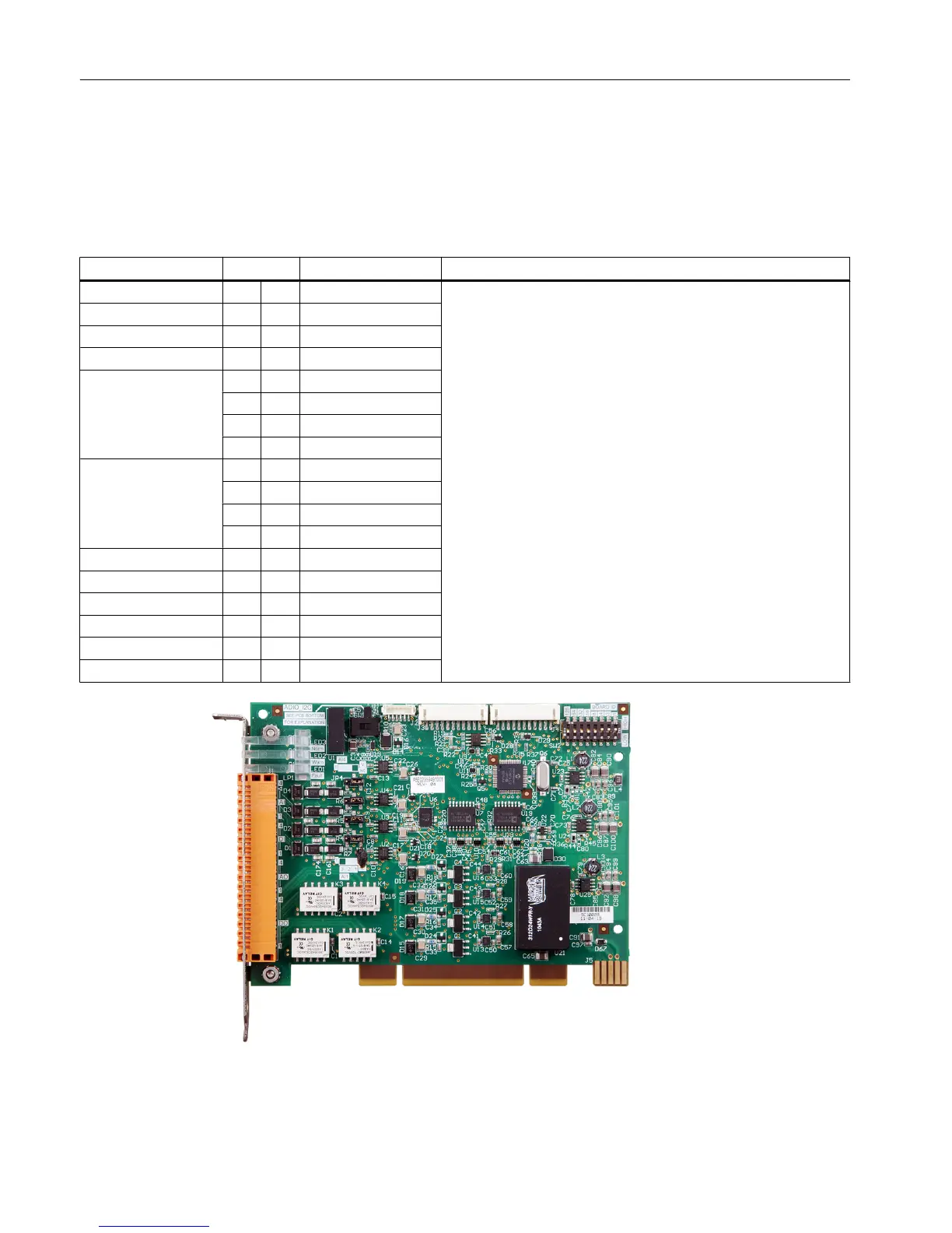
Figure 2-25 Analog and Digital I/O Board (ADIO_I2C)
Electronic Compartment Component Descriptions and Maintenance Procedures
2.4 Analog and Digital IO
Maxum II Reference Manual
60 Manual, 7/2017, 2000596-001

 Loading...


