2.2.3.4 Onboard Solid State Relays
Low-Wattage Heater SSR Control
The PECM has six solid-state relay circuits. These circuits can control low wattage (10 to 250
Watts) air bath heaters, heaters in the heated Flame Ionization and Flame Photometric detector
housings or in heated sample injection valves, and can be adapted for on-off control of a
sample valve or other device. The output voltage from each relay can either be 115 VAC or
230 VAC depending upon the mains supply voltage. Available outputs from the relays are on
TB3 through TB8. Corresponding inputs are labeled LWH1 through LWH6. The LWH6 input
controls the medium wattage heater (MWH) output. When a relay output is used for sample
valve control, the supplied jumpers must be inserted in the corresponding input LWH1 through
LWH4. (See
Additional Relay Outputs
below for using the individual SSRs in outputs 5 and
6.) For safety, since the power switching circuits are primarily designed for low-wattage air-
bath heater control, each circuit has two series-connected SSRs, each being separately
controlled. The jumper ties the two relays together to function as one output when they are not
used for low wattage heater control. The circuitry is similar to the 1400-Watt High Wattage
Heater Power Switching and it is controlled by signals from the Detector Personality Module
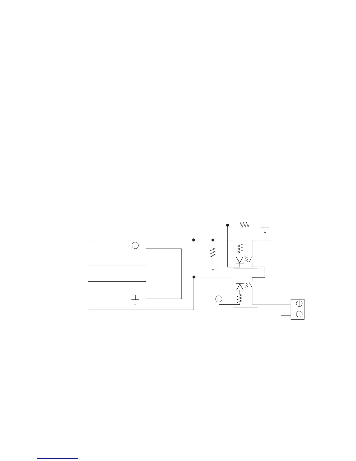
(DPM) heater circuit. The diagram below shows a simplified schematic of the Low Wattage
Heater Relay Circuit LWH4.
Figure 2-7 LWH4 Heater Circuits
Electronic Compartment Component Descriptions and Maintenance Procedures
2.2 Power Entry and Control Module
Maxum II Reference Manual
Manual, 7/2017, 2000596-001 23

 Loading...


