The alarm system can also provide direct information on alarms for an error. Review the alarms
to see if they provide an indication of the problem. Each alarm has a written description that
may provide an indication of the problem area.
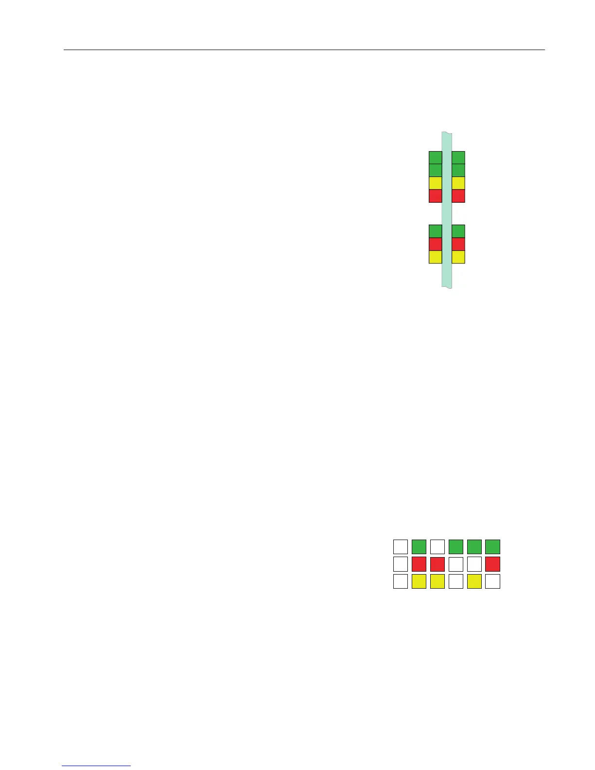
The LEDs on the PECM board can help with
troubleshooting problems. There are two
sets of LEDs: one on each side of the front
board as shown in the diagram to the right.
The bottom set of three LEDs is the same as
used on other boards (described below.) The
left set is for the PECM software. (The other
LEDs are not used for PECM1 replacement.)
The corrective action to take for each of the
LED indications is noted below with a correc‐
tive action reference number on the diagram
at the right. The normal state indication is
shown in the diagram below.
PECM-CTRL PCB
LEFT Heater Status RIGHT Heater status
Heater 1 Air Pressure
Heater 1 Power Activate
Heater 1 Temp Limit
Heater 1 Overtemp
Heater 2 Air Pressure
Heater 2 Power Activate
Heater 2 Temp Limit
Heater 2 Overtemp
Normal
Fault
Warning
Normal
Fault
Warning
PECM Status
Temperature
Controller
Status
PECM LEDs
State 1
1. If all units in this state, then power to the analyzer and/
or board is not active
2. Reset the device or cycle power
3. Check power connections to board (AC and 24VDC)
4. Replace unit
State 1 - Power off
State 2 - Self test
State 3 - Address assignment
State 4 - Normal operation
State 5 - Warning condition; data good temporarily
State 6 - Fault condition; data invalid
Normal
Fault
Warning
PECM LED Interpretation
State 2
1. Reset the device or cycle analyzer power
2. Replace unit
State 3
1. Reset the device or cycle analyzer power
2. If all modules are in State 3, then SNECON is not
communicating (check cabling and connections)
3. Replace unit
State 4 Normal Operation
State 5
1. Reset the device or cycle power
2. Check communication cable connections
State 6
1. Reset the device or cycle power
2. Check communication cable connections
3. Check for missing Temp Limit setpoint boards
4. Check for shorted or open RTDs
5. Replace the unit
6. Replace other connected units
Electronic Compartment Component Descriptions and Maintenance Procedures
2.2 Power Entry and Control Module
Maxum II Reference Manual
Manual, 7/2017, 2000596-001 29

 Loading...


