5 System Parameters Issue 04/02
MICROMASTER 410 Operating Instructions
54 6SE6400-5EA00-0BP0
Drive Features (P0004 = 12)
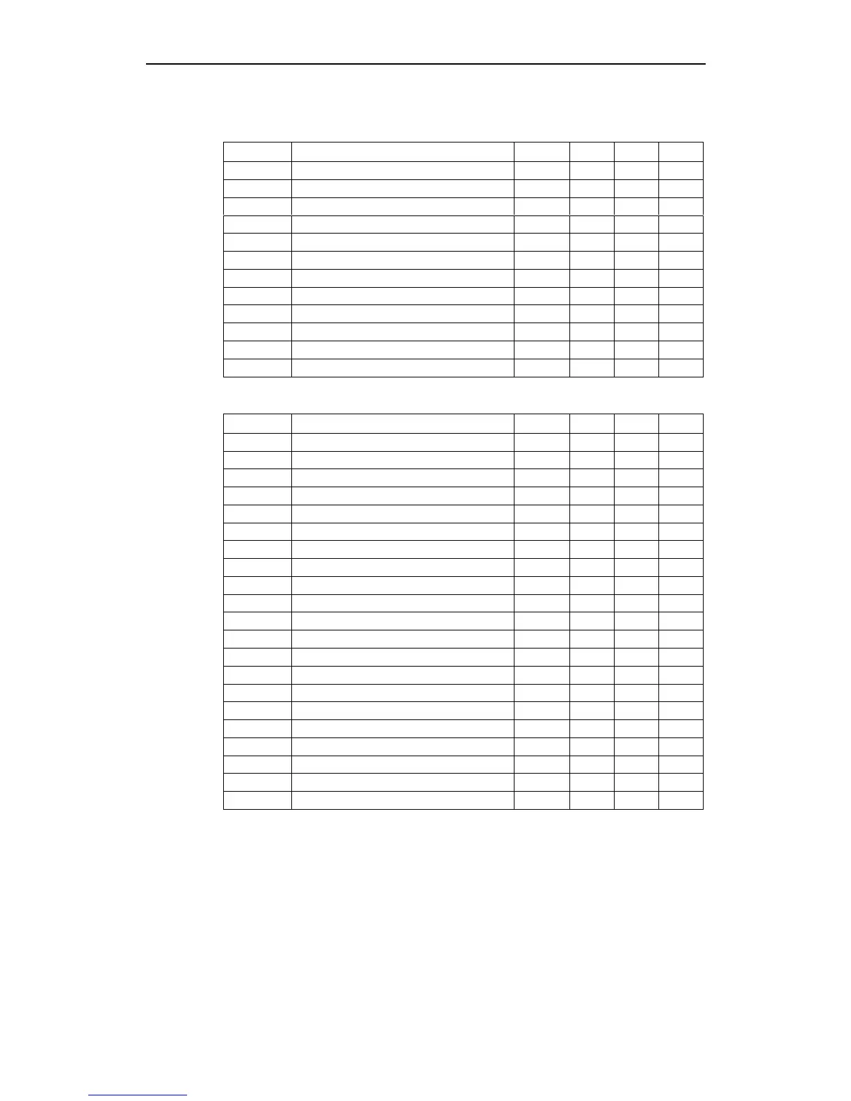
ParNr ParText Default Acc DS QC
P0005 Display selection 21 2 CUT N
P1200 Flying start 0 3 CUT N
P1202 Motor-current: Flying start 100 3 CUT N
P1203 Search rate: Flying start 100 3 CUT N
P1210 Automatic restart 1 2 CUT N
P1215 Holding brake enable 0 3 T N
P1216 Holding brake release delay 1.0 3 T N
P1217 Holding time after ramp down 1.0 3 T N
P1232 DC braking current 100 3 CUT N
P1233 Duration of DC braking 0 3 CUT N
P1236 Compound braking current 0 3 CUT N
P1240 Configuration of Vdc controller 1 3 CT N
Motor Control (P0004 = 13)
ParNr ParText Default Acc DS QC
r0020 CO: Act. frequency setpoint - 2 - -
r0021 CO: Act. frequency - 2 - -
r0022 Act. rotor speed - 3 - -
r0024 CO: Act. output frequency - 3 - -
r0025 CO: Act. output voltage - 3 - -
r0056 CO/BO: Status of motor control - 2 - -
r0067 CO: Act. output current limit - 3 - -
P1300 Control mode 0 2 CT Q
P1310 Continuous boost 50.0 2 CUT N
P1311 Acceleration boost 0.0 3 CUT N
P1312 Starting boost 0.0 2 CUT N
P1316 Boost end frequency 20.0 3 CUT N
P1320 Programmable V/f freq. coord. 1 0.00 3 CT N
P1321 Programmable V/f volt. coord. 1 0.0 3 CUT N
P1322 Programmable V/f freq. coord. 2 0.00 3 CT N
P1323 Programmable V/f volt. coord. 2 0.0 3 CUT N
P1324 Programmable V/f freq. coord. 3 0.00 3 CT N
P1325 Programmable V/f volt. coord. 3 0.0 3 CUT N
P1333 Start frequency for FCC 10.0 3 CUT N
P1335 Slip compensation 0.0 3 CUT N
P1340 Imax controller prop. gain 0.000 3 CUT N



 To Next Page